


|
|
|
TinyTran - another approach to electric actions
Colin Pykett
"The conventional view serves to protect us from the painful job of thinking" J K Galbraith
Posted: 17 February 2014 Revised: 20 February 2014 Copyright © C E Pykett 2014
WARNING
Abstract. This article describes a hard wired approach to electric action circuit design which is more economical in terms of component count than alternatives such as conventional diode keying. Like the latter, it employs switching at two points in each magnet circuit - at the keys and at the coupler gates - but its implementation at a detailed level is significantly different. Instead of using very large numbers of electronic coupler switches each realised using discrete transistors, diodes and resistors, this approach uses miniature telecoms relays for coupling. Keying is then done electronically using a single transistor in each key circuit, regardless of how large the organ might be and how many couplers and unit chests it might employ. Thus the number of transistors in any system always equals the number of keys on the instrument using this method - just one transistor per key. For this reason the approach is called TinyTran to denote a transmission using a smaller number of transistor switches than conventional systems.
By using plug-in relays of the type suggested, maintenance in the field should be greatly simplified. At the same time the compelling advantages of maintainability, graceful failure and resistance to obsolescence exhibited by diode keying are retained. However, because the system uses far fewer components than conventional diode keying, particularly regarding the number of transistor switches required, it should be cheaper because of lower component and assembly costs. It should also exhibit enhanced reliability and survivability for the same reasons.
Contents (click on the headings below to access the desired section)
Electric actions for controlling pipe organs have evolved through three stages. The first lasted from the late nineteenth century to the middle of the twentieth, during which they were implemented entirely electromechanically using relay switching [1]. The second emerged gradually after the 1960s when electronic components such as silicon diodes and transistors began to displace electromechanical relays, and this type of system is still installed today under the name of 'diode keying' [2]. The third stage began in the 1980s when the appearance of microprocessors made possible software control of the action instead of the fully hard wired systems used hitherto. These systems are now employed widely.
None of the three approaches is ideal as they each have weaknesses as well as strengths. Both of the hard wired approaches (electromechanical and diode keying) are fundamentally simple in terms of the basic switching elements employed, but complex in terms of the very large numbers of switches required and their interconnections. This means that the assembly of numerous though quite cheap components is time consuming and labour intensive, therefore it accounts for a significant part of the installed cost. However they are readily maintainable without requiring specialist knowledge beyond that possessed by any competent organ builder, and they are not subject to rapid obsolescence. Moreover, when they do go wrong they usually fail gracefully in the sense that total and catastrophic failure is rare. More often, the odd note or stop fails from time to time rather than the whole system. Computer based transmissions in some respects lie at the opposite pole - they are not conceptually simple, though they involve less hardware. However because of their proprietary nature (there is no commonality between the products of different manufacturers) and the fact they rely on software hidden within microprocessors, they can be difficult if not impossible to repair. This problem is exacerbated by the rapid obsolescence which afflicts all computer based systems. Thus replacement of the entire transmission at significant cost, rather than its repair, is sometimes an inevitable consequence if the system breaks down. Failures also tend to be catastrophic, with the whole system going down at once rather than just parts of it.
Against this background, this article takes a fresh look at the issues and proposes another approach. It adopts a hard wired rather than a software-driven solution because of the compelling advantages of maintainability, graceful failure and resistance to obsolescence. However it is far more economical in terms of component count than is diode keying, particularly regarding the number of transistor switches required, thus it should be cheaper because of lower component and assembly costs. It should also exhibit enhanced reliability and survivability because fewer components are employed.
Unlike the articles referred to already ([1], [2]) which were written at an illustrative level for the non-specialist, this one is aimed more at those who have a good understanding of electric organ actions and of electronics. This does not mean it should not be read by anyone else, but its style is more concise and targeted at those with more experience simply to constrain its length.
There are two main switching requirements in any type of hard wired organ action. The first is to switch several circuits at each key. The use of independent circuits is necessary to prevent undesirable phenomena such as unwanted notes sounding and current back-flow, and in electromechanical systems the several circuits are controlled by multiple key contacts. In most diode keying systems only a single key contact is employed, usually feeding multiple diodes or transistors which provide the necessary circuit isolation. The second requirement is to gate the current (switch it on or off) in any of the keyed circuits at will, depending on which couplers are drawn at the console (and speaking stops as well in the case of unit organs where extension or borrowing is used). This involves the use of coupler relays with many contacts in electromechanical systems, or large numbers of solid state switches in diode keying.
The system described in this article is no different at this top level of implementation in that the keying of multiple independent circuits followed by coupler switching is still used. However its realisation is significantly different at the component level. To understand why, it is necessary first of all to review how electromechanical relays have evolved. The coupler relays (ladder switches) used in traditional electromechanical actions pull in many contacts (typically 61 or so) when a single, large electromagnet is energised. Aside from reliability issues, the problems with these relays include their upfront cost and the fact they are highly labour intensive in terms of hand wiring when an action is being installed. This adds yet more to the customer's bill. Also they are specialised items serving a small and declining market, and although they can still (early 2014) be obtained it would be unwise to assume this will continue to be so indefinitely. Therefore it would be unthinkable to incorporate them in a new action today.
However this does not mean relay technology of any type is dead in the water. In applications where their switching speeds are acceptable, and this includes organ actions, modern relays can be very cost effective. Therefore relays still sell in their countless millions, and the fact they are now so cheap and reliable confirms this. So if the electronics industry at large uses relays in substantial numbers, there is a case on the face of it for re-introducing them into organ actions. This is because, without doubt, they are by far the simplest way of implementing the hundreds of AND gates which lie at the heart of coupler switching. Therefore it is suggested in this article that an electromechanical coupler switch be made by using as many miniature industry-standard relays as necessary instead of numerous discrete solid state switches, each of which occupies a significant PCB footprint populated with several diodes, resistors and at least one transistor. Thus the component count and size of the PCBs can both be reduced by using suitable relays. This implies a cost benefit in itself, which will be augmented by likely reductions in assembly times. Moreover, relays of the type envisaged will plug into cheap DIL sockets, considerably simplifying fault finding in the field and greatly improving maintainability. An organ builder would surely find it more attractive to plug a new relay into a socket than struggle to solder a new transistor into a crowded PCB which cannot be removed from the organ.
The decision to use state of the art relays for coupler switching leads to a second important benefit which does away with the need for a separate switching transistor for each electromagnet in the action in some cases (this benefit would be particularly substantial in organs which are partly or fully unified because of their large numbers of magnets). Instead, it is proposed that transistor switching is done at an earlier stage in the system - in the keying circuits. Thus in the system discussed here, each key contact controls a single medium power transistor which then switches the currents in multiple circuits via medium power diodes. The current in each circuit can be up to 1A, which will pass straight through the coupler relays and energise the corresponding magnets directly without needing further transistor drivers. Most if not all heavy duty magnets in direct electric actions can therefore be controlled, besides the smaller chest magnets used in electropneumatic actions. The presence of the keying transistor means that only a single key contact is required, and its current gain results in only small currents needing to be switched at the keys themselves, just as with traditional diode keying systems. This approach does away with all the transistor circuits in the coupler switches of a conventional diode keying action. In addition, the number of transistors and their ancillary components would be further reduced by a huge factor in a fully unified organ, which contains far more magnet circuits than does a 'straight' organ using slider chests. These advantages arise because the number of transistors in the entire system simply equals the number of keys on the organ - only one transistor per key is needed - regardless of its size and of how many magnets, couplers and unit switches it might contain. For this reason the approach is called TinyTran to denote a transmission using a smaller number of transistor switches than conventional systems.
The outline just given of the approach to coupler switching and keying will now be expanded.
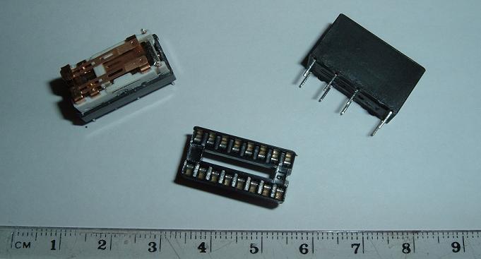
Figure 1. A BT47 style relay
It is suggested that BT47 style miniature telecoms relays are used to implement coupler switching. Illustrated in Figure 1, they are barely bigger than one's thumb nail, occupying the same PCB footprint as a 16 pin DIL socket (also shown) into which they can be plugged. This is an attractive alternative to soldering them into the board on account of the major improvement in system maintainability which will result. They are totally sealed (the example at top left of the picture showing the contacts had to have its top physically sawn off), therefore dust and atmospheric contamination of the contacts is not an issue. They have dual contacts arranged in a DPDT/DPCO configuration, thus the number of relays required equals only half the number of circuits to be switched, and each relay will typically switch 1A per contact. This is ample for controlling the heavy duty magnets used in direct electric actions (typically these have a 30 ohm coil for use on a 15V supply, thus they draw 0.5A), and well in excess of that required for the chest magnets in electropneumatic ones. All magnets must be diode-suppressed of course. The availability of changeover contacts could be neatly exploited in applications such as transferring a reed unit between two manual divisions under the control of a "Choir Reed on Great" type of stop, and discussion of this example will be expanded later. In medium quantities (250+) they cost around one US dollar, and they are sourced by many manufacturers through component suppliers such as Rapid Electronics and RS Components in the UK. Therefore they are a cost-effective option for implementing coupler switches.
An inter-divisional coupler with 61 switches would therefore require 31 relays. They are available with various coil voltages, though the 12 volt version would probably suit most organs. With this voltage option the coil resistance is typically 400 ohms, thus the relays in the complete coupler would consume nearly 1A. This current would be switched by the corresponding stop key or draw stop, either directly if its contacts were up to it, or via a transistor or an additional relay. Only one suppressor diode would be required for all 31 relay coils because they are wired in parallel. Unless the organ action itself operated close to 12V, it would be prudent to include a resistor in the coil circuit to avoid the possibility of reducing relay life by over-driving them. This resistor would typically be 2.7 ohms/3W for 31 relays with 12 volt/400 ohm coils operated from a 15V action power supply.
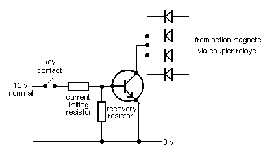
The keying circuit switches the action magnets directly, via the coupler relays described above, using a single medium power transistor controlled by a single key contact. Mutual independence between the switched circuits is achieved by using multiple medium power diodes in the collector circuit. The arrangement is sketched in Figure 2.
Figure 2. Keying circuit
The action magnets (not shown) are all connected to the positive supply rail, and those for which a coupler relay switch is closed will then be energised via a diode when the key contact closes. As many magnet circuits as desired can be switched by the transistor provided its collector circuit is not overloaded. There is a wide choice of transistors (NPN of course) which will do the job here, but a modern variant of the 2N3055 range would be as good as any in many applications. This old workhorse has been around for half a century and it is cheap and widely available. The TIP3055 variant would be convenient to accommodate on a PCB because its package (typically TO-218) would not occupy much real estate on the board, and it would not require a heat sink in this switching application. It will switch as many circuits (magnets) as could reasonably be required. For example, 10 heavy duty lever magnets each passing 500 mA at 15V (i.e. 30 ohm coils) could be handled with ease by this transistor. At this value of collector current (5A) its current gain would typically be about 50, meaning that the key contact would have to switch about 100 mA. If this was deemed too high, a power Darlington transistor could be used instead which would require an input current of only a few mA. However the example just given is perhaps rather extreme, and if only high-resistance (c. 150 ohms) chest magnets for an electropneumatic action were to be switched, a lower-power transistor could be selected if desired. This brief discussion illustrates the flexibility and wide field of application of the system.
The current limiting resistor in the base circuit would be determined by the specific transistor chosen. This also applies to the recovery resistor, whose function is to ensure discharge of the base circuit when the key contact opens. The resistor values are calculated so that the transistor is driven into saturation with the maximum load applied (i.e. all magnet circuits active via their coupler relays). The values would also need to be chosen to prevent damage to the base-emitter junction when there was no collector load, that is when no magnets were being switched (all couplers off). Alternatively or in addition, a dummy load resistor (in series with a diode) could be placed in the collector circuit in parallel with all the other diodes to ensure that the transistor will always switch on and draw collector current when the note is keyed, even if no magnets were active. However, if the transistor controlled the magnet in a slider chest, this would not be gated via a coupler relay and therefore it would always provide a default collector load even when all the other magnet circuits were inactive. In this case a dummy load would be unnecessary.
The point of labouring the foregoing issue is that a transistor is not a transistor at all if its collector is left floating. In the absence of transistor action, the fragile base-emitter circuit is simply a forward-biased diode which can be easily damaged by excessive current. In view of the possibly rather high currents handled by the keying transistor in this application, it is important to configure the circuit robustly so that transistor failure through inept design does not occur.
The diodes are medium power varieties which should desirably handle at least 1A, such as the 1N4002. These should also be used throughout the entire keying system for magnet suppression. This is mentioned because they have to handle an instantaneous peak current at key release equal to the static current drawn by the magnet while it was energised. This will be at least 100 mA for electropneumatic chest magnets, and up to 500 mA for direct action magnets or solenoids. I have seen systems where 1N4148 signal diodes were used as suppressors, which will handle less than 20 mA before failing!
Drawing together all of the foregoing, some complete circuits are now given as examples of how the system works. They include inter-divisional couplers, unit chest control and transferring stops between manual divisions. In all cases only one transistor per key is required.
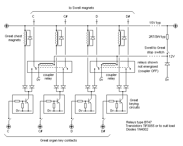
Inter-Divisional coupling - Swell to Great The keying and coupling circuits for four consecutive notes of an inter-divisional coupler (Swell to Great) are shown at Figure 3.
Figure 3. A "Swell to Great" inter-divisional coupler - wiring diagram for four consecutive notes
The diagram relates to an organ with slider chests, in which the chest magnet corresponding to each key is always activated when its contact closes, regardless of whether any couplers are drawn. (This differs from unified instruments, in which magnets are only activated when speaking stops are drawn). Therefore the Great chest magnets are not gated by a coupler relay switch. Only the Swell organ magnet currents in this example pass through the coupler relays, which would also be true for any other coupler.
The simplicity of this circuit in terms of component count can be contrasted with that for an inter-divisional coupler using a more conventional form of diode keying (see Figure 8 in reference [2]).
Although in this simple example each key controls only two circuits, there is no practical limit to the number which can be employed provided the transistor is chosen correctly.
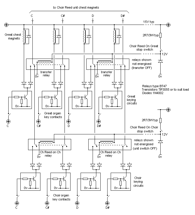
Transfers - Choir Reed on Great A quite different and more complex example will now be discussed. It illustrates how the control of unit chests is achieved, as well as how to transfer that unit from one manual division to another. The example chosen is the "Choir Reed on Great" type of stop. A circuit for four consecutive notes is shown at Figure 4, which now uses the changeover (double throw) contacts on the BT47 relays to implement the transfer.
Figure 4. A "Choir Reed on Great" stop transfer - wiring diagram for four consecutive notes
In Figure 3 the chest magnets of the destination (Swell) division were shown connected to the common connections of the relay changeover contacts, rather than to the normally open contacts. This was unimportant in Figure 3 because the circuit would work either way. However the choice was deliberate because it results in a circuit topology endowing additional flexibility in some other applications. Pursuing this, instead of the destination of this switch being the Swell slider chest shown previously, it is now a Choir reed unit chest as in Figure 4, and the former Swell to Great coupler is now a "Choir Reed on Great" transfer stop. The previously unused normally closed contacts on this switch in Figure 3 are now connected to the Choir organ keying circuits, therefore energising the relays transfers the reed unit from the Choir to the Great organ. Additional switching is also necessary on the Choir organ to enable the reed unit to be selected on that division (the necessary relays are operated by the "Choir Reed on Choir" stop switch).
Implementing a transfer would necessarily be different using the conventional approach to diode keying, because there is no direct electronic equivalent of the changeover contacts which are realised so easily with relays. In this application the use of the changeover contacts illustrates a simple way to allow the reed to be used on only one division at a time rather than both, should this be desired.
Thus, to be clear, the system operates as follows:
1. If "Choir Reed on Choir" is drawn and "Choir Reed on Great" is not drawn, the reed can be played from the Choir only.
2. If "Choir Reed on Great" is drawn, the reed can be played from the Great only. It cannot be played from the Choir regardless of whether "Choir Reed on Choir" is drawn or not.
Note that controlling the additional magnets of the unit chest has been achieved without requiring further transistor switches - it is still only necessary to use one transistor per key in this example. This always remains the case regardless of system size and complexity.
Some practical issues now merit discussion to round off the article, as follows.
Unlike conventional diode keying systems in which some of the tracks on the PCBs carry very small currents, this system requires boards designed to handle significant currents up to about 500 mA in many of the conductors, though often it will be less depending on the current demand of the magnets being switched. This is not a particular difficulty but it needs to be borne in mind when designing the board layouts - the track widths must be chosen appropriately.
It is considered that the system described here is reasonably future-proof. It uses only discrete industry-standard components which have been available for many years or even decades, but this does not mean that the currently happy situation will continue indefinitely. The only practical way to ensure that spares will always be available for any electronic system which must have a long service life (in excess of 20 years, say) is to lay in enough of them at the outset. However this has the advantage that their unit prices, already low, will become even more so if sufficient are purchased to cover anticipated future maintenance requirements.
I do not sit very close to those who regard impeccably laced and soldered wiring harnesses in an organ as some sort of higher art form, attractive though they might look. To my mind, spending too much time on such matters nowadays is a waste of effort and money which only inflates the cost to the customer for no good reason. It also renders alterations or repairs to the wiring difficult if not impossible. Today I see no reason why IDCs (insulation displacement connectors), ribbon cable and other approaches to structured cabling should not find wider application both in consoles and in the organ chamber itself. This does not imply they are never used, but rather that they are perhaps not used often enough.
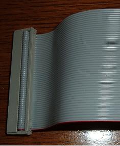
Figure 5. An IDC (insulation displacement connector) terminating a 36-way ribbon cable
An example of a 36-way ribbon cable terminated in an IDC connector is shown in Figure 5. Just two such cables would carry all the connections to and from keyboards, slider chests and many unit chests leaving some wires (prudently) spare, though many different widths are available to match specific needs. Mating the cable and its connector takes only a few seconds, using either a special tool or simply a small vice. Contrast this with the time and skill required to cut, strip, trim and solder 36 wires to a pin board by hand - and then lace them up afterwards! It is therefore suggested that IDC pin headers be incorporated on the PCBs, or mounted on a separate cabling panel nearby, so that cost-effective techniques such as these can be used. Alternatively or in addition, Krone or 110-block connectors could be used for other forms of structured cabling. From an aesthetic point of view there is no reason why these cabling methods should lead to ugly-looking results. On the contrary, there is no excuse for the festoons of unsupported ribbon cables one sometimes sees in electronic equipment. They can be folded, secured and cut to length quite easily with minimal effort, and the cable combs and channels for the individual wires used with Krone-type connector systems also lead to a professional appearance almost automatically. If one is going to use telecoms relays, one might as well use telecoms cabling techniques as well!
So far little has been said about key contacts other than they only need to close a single circuit feeding the base of the switching transistor. However several important practical issues arise in conjunction with the common wire-and-wiper type of contact assembly, and these merit discussion because it is important to maximise contact reliability.
It is possible to increase reliability by a considerable factor through the incorporation of electrical redundancy in the form of multiple contacts wired in parallel. Thus instead of using a single contact wire at the key, a pair of wires will always improve performance by a significant factor. Simple probability theory demonstrates this - consider a case in which a single wire-and-wiper contact has a one in four chance of failing on average, in other words it has a 75% chance of working. This would be unacceptable for organ applications because it would mean that if you pressed a key four times in succession, on average you would get no response in one case. Yet by using two wires instead of one the probability will rise to nearly 95%. This means that a pair of unacceptably bad contacts will become nearly infallible when operated together. The reason is simple of course - using two wires means that the probability of both failing to conduct at the same time is lower than that for each wire separately.
Therefore it is recommended that, when the usual wire-and-wiper type of key contact is employed, contact blocks with at least four wires should be used. Two would be connected to the supply and two to the transistor switch. Each pair is wired in parallel.
Redundancy of this type is used in high quality switches and relays where bifurcated contacts are often found, and they can be seen in the photograph of a BT47 relay in Figure 1. Robert Hope-Jones realised this over 120 years ago when he used redundant contacts in several of his organ mechanisms, one type being a simple wire loop which provided two points of contact with a wiper bar rather than just one. But then, he was a telephone engineer, and we are still discussing the type of telecoms technology he would have found familiar in this article today!
As to contact materials, silver will be generally reliable provided a high enough voltage is used. Below about 6 volts the layer of tarnish which builds up presents a high resistance to the passage of current, whereas it drops off rapidly above this figure. (The effect is called quantum tunnelling). This means silver should never be used if the common 'logic' level of 5 volts is employed, and in this case gold-clad wire must be substituted. Thus I prefer to key at the 15 volts or so at which organ actions commonly operate, and this was indicated above in the schematic diagram of the keying circuit (Figure 2). However it is important to include fuses in the circuits feeding the key contacts because of the high currents available from organ power supplies. If this is not done it is all too easy to cause an accidental short circuit when adjusting the keys or their contacts if a screwdriver, say, falls across them. In these circumstances major damage can ensue if the keyboard supplies are not protected by fast-acting fuses. Separate fuses should be incorporated for each keyboard and any other console assemblies which switch the action current, such as draw stop/stop key contacts and combination pistons. This is an area where it is most definitely better to be safe rather than sorry.
This article has described a hard wired approach to electric action circuit design which is more economical in terms of component count than alternatives such as conventional diode keying. Like the latter, it employs switching at two points in a magnet circuit - at the keying circuits and at the coupler gates - but its implementation at a detailed level is significantly different. Instead of using very large numbers of solid state coupler switches each realised using discrete transistors, diodes and resistors, this approach uses miniature telecoms relays for coupling. Keying is then done electronically using a single medium power transistor in each key circuit, regardless of how large the organ might be and how many couplers and unit chests it might employ. Thus the number of transistors in any system simply equals the number of keys on the instrument - one transistor per key - using this method. For this reason the approach is called TinyTran to denote a transmission using smaller number of transistor switches than conventional systems.
By using plug-in relays of the type suggested, maintenance in the field should be greatly simplified. At the same time the compelling advantages of maintainability, graceful failure and resistance to obsolescence exhibited by diode keying are retained. However, because the system uses far fewer components than conventional diode keying, particularly regarding the number of transistor switches required, it should be cheaper because of lower component and assembly costs. It should also exhibit enhanced reliability and survivability for the same reasons.
1. "Electromechanical Keying Systems - Wiring Diagrams", C E Pykett, 2014 (an article on this website).
2. "Diode Keying Systems - Wiring Diagrams", C E Pykett, 2014 (an article on this website).
|