


|
|
|
Diode Keying Systems - Wiring Diagrams
Colin Pykett Posted: 10 February 2014 Revised: 10 February 2014 Copyright © C E Pykett 2014
WARNING
Abstract. This article shows how fully electronic organ actions can be assembled from basic components including diodes and transistors using the technique known colloquially as 'diode keying'. A coupler switch is described in terms of a diode AND gate, and it is also explained how an electromagnet can be driven using a transistor. Using only these two types of generic circuit module, it is demonstrated that a wide range of actions can be constructed to suit any organ with any mix of intra- and inter-divisional couplers.
Achieving isolation between various circuits is a necessary feature in any type of organ action if unwanted notes are not to sound, and it is shown how diodes are well suited to this role. They also enable the use of a single contact per key which only has to switch a small current regardless of the size and complexity of the organ. Thus only one wiring harness from each keyboard is necessary to connect the console to the organ itself.
It is pointed out that, given a systematic approach, identifying and replacing faulty components in a diode keying system is no more difficult than it was in the days of electromechanical actions. This is not necessarily the case with other types of electronic transmission. For such reasons diode keying sits well with the conservative technology and dignified longevity expected of a pipe organ, and it is for this reason that the article was written in the hope that it might assist those who wish to understand more about how it works.
Contents (click on the headings below to access the desired sections)
Another article on this site discusses in detail the wiring diagrams applicable to the electromechanical keying systems which were first used for controlling pipe organs with an electric action [1]. Invented by Robert Hope-Jones in about 1890, they remained in exclusive use across the world for some seven decades with little modification. However in the 1960s they gradually began to incorporate solid state electronic components, particularly silicon diodes and transistors, once these became more reliable and cheaper than hitherto. Eventually all of the older electromechanical components such as relays were entirely supplanted by electronics, and this type of action became known in some quarters as 'diode keying' to distinguish it from 'electromechanical keying'. The name may have been borrowed from the electronic organ world which also developed its own variants of diode keying around the same time. A decade or so later, the next step for both types of organ was the introduction of computer control in the form of microprocessors, in which all the binary logic operations were implemented using software (i.e. the programs inside the microprocessors) rather than hardware. MIDI also made its debut at this time (the early 1980s). However diode keying systems for pipe organs still (early 2014) exist widely and they can still be obtained from some organ supply houses and specialist suppliers as an alternative to actions which use computer control.
This article discusses some typical circuits used in diode keying systems. Unlike the older electromechanical actions in which there was little opportunity for introducing circuit variations, there are several or many ways in which the necessary functions can be performed using electronics. Therefore it is only possible to illustrate generic or representative circuit configurations here. The article does not go further to cover computer controlled systems at all in view of their complexity and proprietary nature - the products of all manufacturers differ not only in detail but also at an architectural (system) level, thus there is no commonality between them. Computer-based systems are also subject to rapid obsolescence, which means that changes to their hardware and software can and do occur frequently on a timescale of months or even less. Diode keying systems are less affected by obsolescence because they are built from industry-standard discrete components which have been around for some decades, a situation which will likely persist indefinitely into the future. This is because since the mid-twentieth century it has always been possible to obtain a wide range of discrete devices such as transistors, diodes and resistors. Although particular items (such as transistors having specific type numbers) might disappear from the catalogues from time to time, hitherto it has always been possible to obtain equivalents, and these are invariably of better performance and often cheaper as well. The diodes themselves have been around for over half a century and today they cost virtually nothing in quantity - the price one pays is more for taxes, packaging and shipping rather than for the items themselves. Therefore the descriptions in this article of how diode keying systems work at a circuit level should be reasonably future-proof, like the systems themselves.
As with their electromechanical forbears which contained hundreds or thousands of contacts interconnected with many fat wiring harnesses, diode keying systems contain similarly large numbers of basic electronic components such as resistors, diodes and transistors. Integrated circuits might be used in some systems to cut down the size and component count on the printed circuit boards (PCBs). However the number and sizes of the wiring harnesses are both significantly smaller than in electromechanical systems because the use of diodes, in particular, enables considerable economies to be effected. The technical reasons for this will be explained later. Also many of the interconnections which formerly would have been wired by hand are laid down as multiple parallel tracks on the PCBs themselves. Nevertheless, the use of diode keying with its large number of components is sometimes regarded as old fashioned by those who prefer computer control of an organ action, though it should be remembered that it is far easier to find and remedy faults in a diode keying system than in a computer-based one. Given a systematic approach, identifying and replacing faulty components is no more difficult than it was in the days of electromechanical actions. By contrast, computer-based systems are commonly unrepairable, especially the older ones, and total replacement at considerable expense is then often the only option. For such reasons diode keying sits well with the conservative technology and dignified longevity expected of a pipe organ, and it is for this reason that I have written this article in the hope that it might assist those who wish to understand more about how it works.
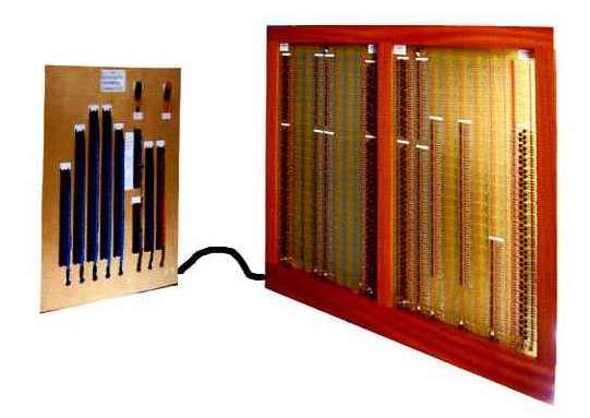
Figure 1. A diode keying system (courtesy Kimber-Allen UK Ltd)
A typical diode keying system offered by a well known supplier of organ parts is illustrated in Figure 1, though it should be understood that each system is ordered as a bespoke custom built item for a particular organ. Because it is rare for two organs to be identical, their keying systems will differ also. The system illustrated consists of a number of sizeable printed circuit boards containing large numbers of components, the boards being mounted in wood frames to protect them and to facilitate installing them inside an organ or organ console. To assist the organ builder, the boards are supplied connected to separate pin panels from which cables are then taken to the various key and stop contacts in the console, and to the electromagnets which are to be controlled inside the organ. A heavy duty low voltage DC power supply (not shown) is also necessary to provide power to the system.
The most important components used in diode keying are diodes (naturally) and transistors, typical examples of which are shown in Figure 2.
Figure 2. Typical components used in diode keying systems
Two types of diode are often incorporated in the same keying system - low and medium current versions which will handle up to about 15 milliampères (mA) and 1 ampère (A) respectively. Diodes pass current only in one direction, always from the unmarked end (called the anode) to that identified with a circular band (the cathode). The low current type is used only in logic circuits such as the AND gates which form an important part of a diode switching system. These will be explained later. The higher current type can also be used in logic circuitry, but in addition they will pass sufficient current to supply heavy duty electromagnets directly which typically consume around 500 mA. This type of diode is also used in large numbers to act as suppressors for magnets of all descriptions. Suppressors are mandatory in diode keying circuits, because they prevent the high back-EMFs generated when electromagnets are switched off from damaging the electronics. In unsuppressed electromechanical switching systems it is these back-EMFs which cause visible sparks at the contacts because they are are in the region of hundreds of volts or even more, the particular voltage figure depending on the amount of energy stored inductively in the field of the magnet concerned.
Two types of transistor are also illustrated, again with different current-handling capabilities. The medium power type is employed to switch the chest magnets used in electropneumatic actions, and (if properly chosen and used) they will also cope with the larger currents required by the heavy duty magnets used in direct electric actions. Occasionally a higher current capability is required, for example to drive multiple heavy duty magnets simultaneously when several are ganged together to work a very large pallet, and in these situations a larger transistor is necessary. That shown at the bottom right of the picture will do this job with ease, though often a somewhat smaller transistor having an intermediate power rating will suffice.
The basic circuits used in diode keying are fairly simple, the apparent complexity of a system arising only because of the large number involved which are repeated many times over on the PCBs. However bear in mind that the circuits to be described in this article have been stripped down deliberately to their bare essentials so that the way they work is not obscured. Therefore in practice the circuits actually found in a commercial keying system might be somewhat more complicated. One reason for this is to compensate for the voltage drop of about 0.6 volts across a silicon diode when it is passing current in the forward direction from anode to cathode. Thus if a particular current path involves several diodes in series, the voltage can be reduced to a level at which the operation of succeeding stages of the circuit might become unreliable. For this reason additional buffer transistors are sometimes incorporated to compensate for the diode voltage drops. This is a particularly important practical point if the circuits operate on low supply voltages such as the standard 5 volt power rail used in many 'logic' systems. For simplicity, in this article all diodes are assumed to be ideal, with no forward voltage drop, but it is emphasised this is unrealistic.
It is useful to first review the basic operations performed by an electromechanical action, because these have direct analogues in diode keying. Therefore if you are unfamiliar with electric organ actions you might like to scan reference [1] first.
In both electromechanical and diode keying systems there are two basic requirements. The first is to activate multiple circuits simultaneously when a key is pressed, such as the circuit which supplies current to the chest magnet corresponding to that key as well as the additional ones feeding all the couplers. The second requirement is for a switch which, for example, brings a coupler into operation when the appropriate coupler stop key or draw stop is operated. These will now be discussed in turn.
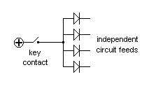
Just as with electromechanical keying, the multiple circuits used in diode keying must not mutually interact. Otherwise one gets currents flowing in unwanted conductors, sometimes in the wrong direction, which results in rogue notes sounding and other unwelcome effects. In electromechanical systems the necessary functional isolation between circuits is achieved by using multiple key contacts, either placed physically at the key or remotely in a key relay. However in diode keying it is the diodes themselves which provide the necessary isolation because they only conduct current in one direction, therefore achieving independence among multiple circuits is beautifully simple when diodes are used, as shown in Figure 3.
Figure 3. Diode keying of multiple circuits
A single key contact can drive as many diodes in parallel as desired, each of which can then feed a separate circuit without interactions taking place between any of them. This is because the one-way action of a diode prevents currents from elsewhere in the system flowing backwards down unintended conductors, thus no circuit 'knows about' the existence of any other. Moreover, an additional practical advantage is that the diodes themselves can be placed remotely at any reasonable distance from the keyboard - typically they will be on one of the PCBs constituting the diode keying system. Thus only a single wiring harness containing typically 61 wires is necessary for each keyboard, regardless of how large and complicated the organ might be.
Many separate switches need to be brought into operation when a coupler is drawn at the console, one for each key involved. Typically 61 switches will be necessary for an inter-manual coupler such as the Swell to Great, and 49 for an intra-manual coupler such as the Swell Octave (the lower figure applying here because the top octave of keys have nothing to couple to). Here we consider each of the switches as an AND gate, regardless of the type of technology used to implement the switch.
Figure 4. A generic electrically-controlled switch
Consider the generic electrically-controlled switch sketched in Figure 4 having two inputs ('in' and 'control') and one output ('out'). This could simply represent an electromechanical switch such as a relay, the 'control' input then corresponding to the connection to its magnet coil. It will be shown in a moment how it could also represent a diode (electronic) switch, but first let us appreciate how it can be regarded as an AND gate. This is important because much of the literature and documentation relating to electronic organ actions refers to switches as logic gates.
The operation of the switch in Figure 4 can be written in the form of an elementary logic equation as:
out = in AND control
This merely means that an output is only obtained when the input AND the control lines are both active. If neither or only one of them is active, no output is obtained. This is the definition of an AND gate. So far so good, but it's not much help considering an electromechanical relay sitting inside the box in the diagram when we are actually considering electronic keying. So what do the internals of the box look like in a diode keying switch? In other words, how do we make an AND gate using diodes?
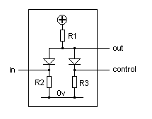
Figure 5. An electronic switch (AND gate) using diodes and resistors
One way to do it is shown in Figure 5. Two diodes and three resistors are employed, and the way it works is as follows. If both the 'in' and 'control' connections are not active (i.e. they are simply left floating as shown), current from the positive line will flow through resistor R1 and then down through both diodes and their resistors. Then the voltage appearing at 'out' will depend on the potential divider formed by R1 in conjunction with R2 and R3. If we make R2 equal to R3 for convenience, and R1 much greater (say 10 times greater) than both R2 and R3, then Ohm's Law shows that the 'out' voltage will be small, lying much closer to zero volts than to the supply voltage.
If either the 'in' or 'control' input, but not both, is now connected to the positive supply voltage line, nothing much will happen to the voltage at 'out'. This is because current can still flow through one of the potential dividers formed by R1 and either R2 or R3. However, if both the 'in' and 'control' inputs are made positive, the potential divider no longer exists because current can no longer flow through R1, since both ends of R1 are now at the same potential This means that the voltage at 'out' now rises to the same positive level as the two inputs 'in' and 'control'. In other words, we have turned our diode switch on, just as we could have turned an electromechanical relay on.
Now we need to consider how to drive an electromagnet, such as a chest magnet in an electropneumatic action, from the output of the diode switch just described. The magnet cannot be connected directly to the 'out' line of the switch (see Figure 5) because this could not supply enough current into such a current-hungry device (a chest magnet requires typically 100 mA and a heavy duty lever magnet 500 mA). This is because the magnet current would have to flow through R1, and because this has a relatively large ohmic value, it would cause a voltage drop which would prevent the magnet working. Therefore what we do is to interpose a transistor between the 'out' line and the electromagnet. The transistor acts as an amplifier which has a high current gain, meaning that it can deliver a large output current for a small input current. Like all amplifiers, it does this by diverting current from the power supply line into the load (the magnet in this case). A typical amplifier circuit is shown in Figure 6.
Figure 6. Transistor driver for driving an electromagnet
The output from the the diode switch (the 'out' line in Figure 5) is connected to the base of the driver transistor through a resistor which limits the current to a value which the transistor will tolerate. A larger current, which equals the base current multiplied by the current gain of the transistor, will then flow into the collector through the electromagnet being controlled. The numerical value of current gain ranges from a few tens to very large figures depending on the type of transistor chosen. A recovery resistor is connected between the base and the zero volts line to assist a rapid switch-off when the input voltage is removed, otherwise the transistor might switch off sluggishly owing to stored capacitive charge in the base circuit. Note the use of the mandatory suppressor diode across the magnet coil to protect the transistor.
We can now put all the previous circuit modules together to arrive at complete schematic diagrams for organ actions incorporating various types of couplers. The type of organ considered is one using slider chests rather than a 'unified' organ using unit chests, such as a theatre organ [2].
An important and useful aspect to bear in mind is that as many coupler circuits as desired can operate any chest magnet, simply by providing a feed for each circuit into the corresponding driver circuit of that magnet. However each feed must use a series diode so that the essential isolation between circuits is maintained. Thus the driver for a magnet on the Swell organ, for example, would always have a feed from its own key. In addition it could also receive a feed from the Swell to Great coupler, the Swell to Choir, Swell sub and super octaves, etc. There is no limit to the number of couplers which can be used, provided their circuits always use series diodes in the feeds to the magnet drivers.
Intra-divisional coupling - octave coupler
The wiring diagram for an Octave Coupler is shown in Figure 7. Before diving into further detail, it is obvious at first glance that diodes are by far the most numerous components in this circuit, which explains why the technique is called diode keying.
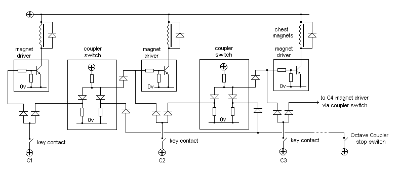
Figure 7. An Octave Coupler realised using diode keying techniques
The circuit shows the lowest note on a keyboard, C1, together with its connections to C2 (the octave above) and thence to C3 (the octave above that). In practice, of course, each key on the keyboard has identical circuitry associated with it. The circuit modules inside the rectangles are the coupler switches and magnet drivers described above (Figures 5 and 6 respectively), and the layout of those diagrams has been preserved here to assist comprehension. Each key on the keyboard (apart from the top 12 which have no octaves to couple to) controls two independent circuits using the parallel diode method shown earlier in Figure 3, one circuit for its own chest magnet and the other for that of the octave above.
Each magnet driver (apart from those for the lowest 12 notes) receives a feed from its own key as well as one from the key an octave below. However the latter feed is only activated when the Octave Coupler stop is drawn at the console. Each driver feed goes via a diode, as mentioned above.
Other aspects of the circuit are:
1. Key C1 switches on its own chest magnet when its key contact closes. It also sends an input to an octave coupler switch module through a separate diode.
2. If the Octave Coupler stop switch at the console is closed, the output of the coupler switch module then activates the magnet of key C2 via its driver circuit. If the Octave Coupler switch is open this does not happen.
3. The Octave Coupler stop switch provides the control input to all the coupler switch modules in parallel.
All of the electronic components would normally be mounted on one or more PCBs, except possibly for the suppressor diodes as these are often fitted at the magnets themselves.
Inter-divisional coupling - Swell to Great
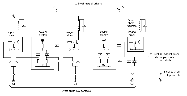
A similar circuit configuration can also be used to implement other types of coupler, such as inter-manual ones (e.g. Swell to Great). In this case the outputs of the coupler switch modules on the Great organ are taken (via the mandatory diodes) to the magnet drivers of the Swell, as shown in Figure 8.
Figure 8. A Swell to Great coupler realised using diode keying techniques
In the examples just given only two diodes per key were used, one for the chest magnet for that key and the other for the (single) coupler. However a key can control as many couplers as desired, simply by adding the necessary number of diodes fed by the key contact. The additional diodes each feed further arrays of coupler switch modules.
This article has shown how fully electronic organ actions can be assembled from basic components including diodes and transistors using the technique known colloquially as 'diode keying'. A coupler switch was described in terms of a diode AND gate, and it was also explained how an electromagnet can be driven using a transistor. Using only these two types of generic circuit module, it was demonstrated that a wide range of actions can be constructed to suit any organ with any mix of intra- and inter-divisional couplers.
Achieving isolation between various circuits is a necessary feature in any type of organ action if unwanted notes are not to sound, and it was shown how diodes are well suited to this role. They also enable the use of a single contact per key which only has to switch a small current regardless of the size and complexity of the organ. Thus only one wiring harness from each keyboard is necessary to connect the console to the organ itself.
It was pointed out that, given a systematic approach, identifying and replacing faulty components in a diode keying system is no more difficult than it was in the days of electromechanical actions. This is not necessarily the case with other types of electronic transmission. For such reasons diode keying sits well with the conservative technology and dignified longevity expected of a pipe organ, and it is for this reason that the article was written in the hope that it might assist those who wish to understand more about how it works.
Grateful thanks are due to Messrs Kimber-Allen UK Ltd for permission to reproduce material from their catalogue.
1. "Electromechanical Keying Systems - Wiring Diagrams", an article on this website, C E Pykett, 2014.
2. A bar and slider chest (or slider chest for short) is one having a single pallet valve for each key which can admit wind to some or all of the pipes corresponding to the same note on the keyboard, depending on which stops are drawn. For the purposes of this article the important point is that only one electric action (direct electric or electropneumatic) is required per key or pallet, regardless of how many pipes are controlled by it. This differs from an organ using unit chests in which each pipe has its own electric action. The two types of chest result in quite different engineering architectures as far as their actions are concerned.
|