


|
|
|
Electromechanical Keying Systems - Wiring Diagrams
Colin Pykett
Posted: 2 February 2014 Revised: 8 February 2014 Copyright © C E Pykett 2014
WARNING
Abstract. This article describes how the electromechanical keying systems used in pipe organs since the time of Robert Hope-Jones in the 1890s were wired. There are still many such instruments around otherwise it would not be possible to obtain the action components today, therefore it is anticipated the article will address the needs of those who wish to maintain, repair or simply understand them. It is also the intention that the article might have some historical value. Circuits applicable to intra- and inter-divisional couplers are described, as well as those appropriate to organs using slider and unit chests. The extension principle is explained at the circuit level, together with some particular issues related to the fully unified organ such as the need for key relays. It is pointed out that well-designed electromechanical actions usually fail gracefully rather than catastrophically, they are readily maintainable, and they are more robust than their electronic counterparts against eventualities such as lightning damage.
Contents (click on the headings below to access the desired section)
Intra-divisional coupling - octaves and suboctaves
The first complete and practical electromechanical control system for pipe organs was invented and first demonstrated in Britain by Robert Hope-Jones in the early 1890s in his organ at St John's church, Birkenhead. Its operating principles as well as many engineering aspects were immediately adopted and used, virtually unchanged in all but minor details, across the world until the 1960s [1]. At that time solid state electronic components (diodes and transistors) began to appear gradually, leading to some circuit simplifications and a class of actions which became known in some quarters as 'diode keying'. However it is remarkable that the older, fully electromechanical, systems not only still exist but that they exist widely. This is evident if only because all of the necessary components are still readily available from organ supply houses at the time of writing (early 2014), over 120 years since they were first conceived, and some of these will be illustrated and discussed later.
There were several reasons for writing this article. One was an inclination to place on public record the way these systems were put together in terms of their circuitry, in view of the important part they have played in the story of the organ. Another was the motivation provided by the number of enquiries I receive from those who wish to repair or modify older organs, or who simply want to understand how they are wired to satisfy their curiosity - one of these correspondents aptly described the activity he was engaged in as "organ archeology". The issues might appear simple at first sight, because anyone can see that an electrical contact underneath a key can be wired to the appropriate electromagnet. However it is tempting to lay down the gauntlet to those who are satisfied with this shallow view by asking them to sketch the wiring diagram of a WurliTzer theatre organ, or a 'straight' organ using both slider and unit chests with lots of couplers! The almost trivial underlying concepts on the one hand and their practical realisation on the other are poles apart in terms of engineering complexity, though not everyone seems to appreciate it. In fact this article could not avoid drawing out the importance of Hope-Jones's contributions to the subject because he was the first to identify and solve many problems related to electric actions, of which their circuitry was but one [2]. It is therefore a matter of regret that the multitude who have since treated him so disgracefully with scorn and contempt obviously lacked the intellectual penetration to realise they were merely projecting their own limitations onto him.
Therefore this article dwells exclusively on the wiring diagrams employed in organs using an electromechanical action because there is a clear need for clarification in this area. However, to keep its length within reasonable bounds it does not cover electronic systems (diode keying), which will be discussed in a later article.
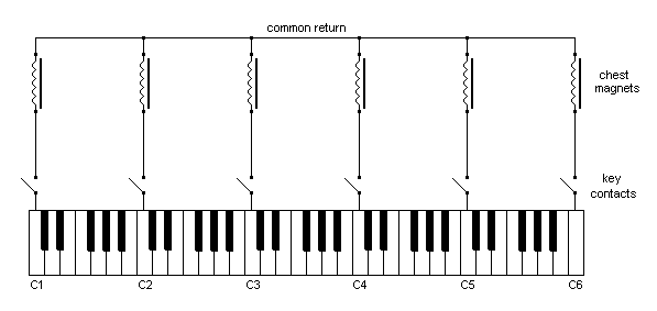
The issues are indeed simple if one considers nothing more than a small one manual 'straight' organ consisting of a single bar and slider chest [3] without any couplers and with a mechanical stop action working the sliders.. In this circumstance each key operates a single key contact, formally described as a single pole single throw (SPST) switch, which is connected to the chest magnet of the corresponding note and to no other. This is illustrated in Figure 1.
Figure 1. Circuit of an electric key action applied to the simplest form of organ
It is assumed that the compass of the organ is five octaves (61 notes), though for clarity only the six C's across the keyboard are shown in the circuit of Figure 1. In reality all of the notes would be connected to their corresponding chest magnets in like manner using a substantial wiring harness comprising 61 individual wires running from the keyboard to the chest.
Intra-divisional coupling - octaves and suboctaves
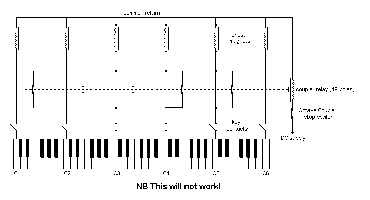
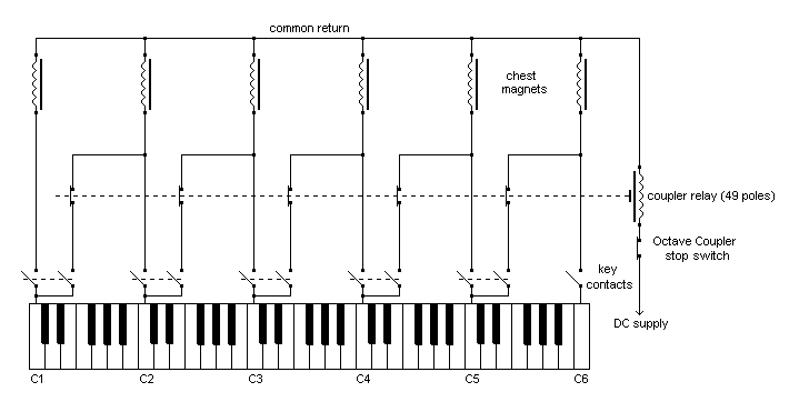
Problems begin to arise when one attempts to do coupling electrically, both intra-divisional (octave or suboctave) couplers and inter-divisional ones such as Swell to Great. Let us consider first adding an octave coupler to our small organ. It might be thought that we can merely wire each key contact to its corresponding note an octave above, so that pressing C1 would also activate the magnet for C2, and so on. Such a scheme in its simplest form is sketched in Figure 2.
Figure 2. A flawed implementation of octave coupling
Setting aside for a moment the inconvenient fact that this arrangement will not work, we observe the introduction of a set of additional switches affecting the cross-connections running between pairs of octavely-related notes. Because there are 61 notes on the keyboard and the slider chest, we only require 49 of these switches instead of 61 because above C5 there are no more chest magnets available to couple to. The diagram suggests that all 49 switches are ganged together mechanically and operated by a single electromagnet, the whole assembly being termed a coupler relay. The relay is brought into action when the Octave Coupler stop switch is closed.
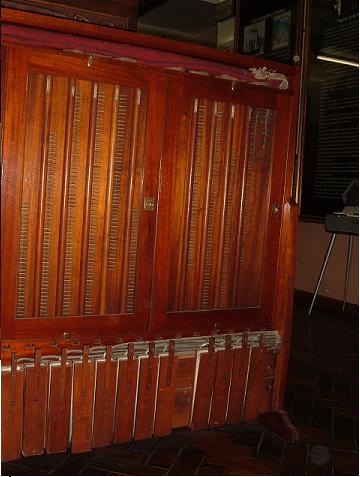
Coupler relays are extremely important in electromechanical actions, because they are used not only for coupling purposes but also for controlling the unit chests used in extension and unified organs. Therefore they appeared at the outset in Robert Hope-Jones's electrical system in the form of an entirely novel electropneumatic coupler relay which he used in many of his instruments. One of his cabinets containing many such relays is pictured in Figure 3.
Figure 3. A Hope-Jones coupler relay cabinet (1894)
Some of the electropneumatic coupler relays formerly inside the large four manual Hope-Jones organ of 1894 at St Paul's, Burton on Trent, now preserved in the Hope-Jones museum of the Lancastrian Theatre Organ Trust in Manchester. Behind the glass doors are vertical dowels containing metal contact pins. These were rotated by means of cranks attached to the pneumatic motors below, thereby bridging corresponding pairs of contacts which were wired from the rear of the assembly. The pneumatic tubing which actuated the motors can be seen, connected to primary electromagnets of the usual Hope-Jones pattern activated via the stop keys. The mechanism was double-acting, with a second set of motors behind the assembly to return the dowels to their original positions. (Copyright © Lancastrian Theatre Organ Trust)
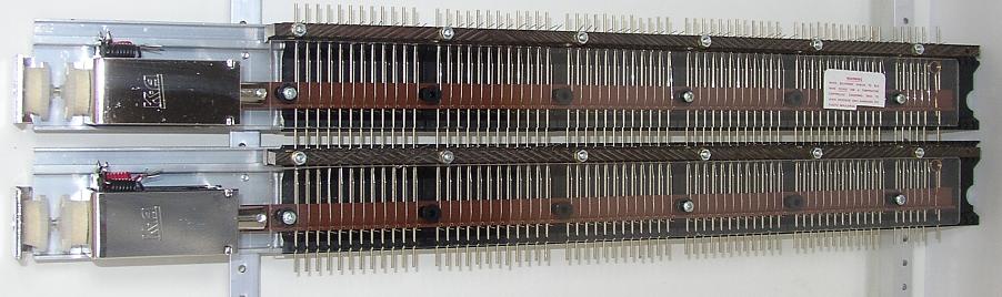
A pair of modern coupler relays, which remain conceptually and functionally identical to those invented by Hope-Jones in the 1890s, is shown in Figure 4. The only major differences are that the contact stacks are actuated by solenoids rather than electropneumatically, and the contact actuators themselves move linearly rather than in a rotary fashion. The most remarkable aspect is that such components can still be obtained at all in today's electronic age, a fact which serves as a fitting testament to the enduring quality of Hope-Jones's thinking and engineering practices all those years ago. For obvious reasons such relays are sometimes called ladder switches today.
Figure 4. A pair of modern solenoid-operated coupler relays (courtesy Kimber-Allen UK Ltd)
But now let us return to the faulty circuit in Figure 2. If a note, say C3, is held down and the Octave Coupler stop drawn, its octave (C4) will indeed sound. Unfortunately so will all the other octaves and suboctaves across the keyboard! Thus playing any of the C notes will result in all the other C's sounding as well, a situation which will also apply to the other note-names (all of the C#'s, the D's, etc). The reason why this occurs should not be difficult to spot from the circuit, which allows current to flow in conductors besides those which are actually desired.
Hope-Jones saw that the only way (in his day) to prevent this was to include additional switches in the form of extra key contacts, as shown in Figure 5.
Figure 5. A workable implementation of octave coupling
The coupler relay is still there, but each cross-connection between octavely-related notes is now controlled or 'gated' by an additional key contact. Each key (apart from the top 12 which have nothing to couple to) now controls two switches, turning the composite keying assembly into a double pole single throw (DPST) switch. One pole of each switch controls the chest magnet for its key, and the other controls that for the octave above via the coupler relay. Hopefully you should be able to see that the unwanted currents which corrupted the intended operation of the previous circuit are now prevented from flowing because the extra key contacts block them.
The incorporation of multiple key contacts was another important innovation of Hope-Jones. It is possible that he himself might have regarded it as trivial on account of the experience he had gained over some years as a senior telephone engineer, where such techniques were necessary and commonplace in the complexity of telephone exchanges. However in the organ world of his day few if any other organ builders would have come across the technique, which can be called 'functional isolation'. These two innovations of coupler relays and functional isolation using multipole switching at once catapulted Hope-Jones head and shoulders above his competitors in the race to develop electric actions of the necessary sophistication. Unfortunately the excess of familiarity built up over more than a century has since bred contempt, with the result that few now pause to ponder on the debt owed to Hope-Jones by the organ world of today.
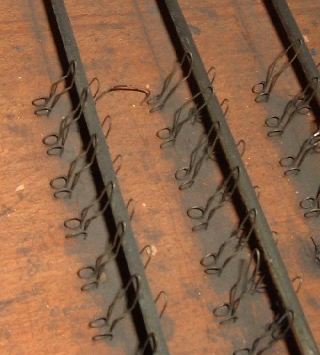
So, as with the coupler relay above, let us have a quick look at examples of multiple key contacts both ancient and modern. Figure 6 shows the type introduced by Hope-Jones in the 1890s.
Figure 6. Multiple key contacts by Hope-Jones providing 'functional isolation' (1899)
Some of the multiple pedal key contacts on the four manual organ of 1898/9 at St Modwen's, Burton upon Trent, whose console is preserved in the Hope-Jones museum of the Lancastrian Theatre Organ Trust in Manchester. The instrument was actually built by Norman and Beard using Hope-Jones's patented components and techniques under license. The manual key contacts are similar though more difficult to photograph. The use of wire loops was another important innovation of Hope-Jones which provided electrical redundancy in the form of two (rather than just one) contact points, thereby improving reliability. (Copyright © Lancastrian Theatre Organ Trust)
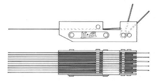
And Figure 7 shows how they have evolved to reach the form more familiar today.
Figure 7. A representative modern key contact assembly (courtesy Kimber-Allen UK Ltd)
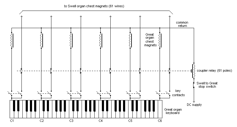
Now that we have covered intra-divisional couplers let us have a look at their siblings, the inter-divisional ones such as Swell to Great. Its wiring diagram (which works this time!) is at Figure 8.
Figure 8. Inter-divisional coupler wiring (Swell to Great)
We can canter through this circuit more quickly on account of having addressed the important issues in detail above when discussing octave coupling. The keyboard and chest magnets in the diagram correspond to those of the Great organ, and the main points are:
1. Multiple key contacts and a coupler relay are both still required, as in the case of octave coupling.
2. The current path to the Swell chest magnets is controlled by the additional key contact for each key. Without this, the coupler would operate both ways - not only would it work as a Swell to Great but a Great to Swell as well.
3. This additional coupling key contact is connected directly to its corresponding Swell chest magnet via the coupler relay.
4. The coupler relay requires 61 pairs of contacts, not 49 as previously with the octave coupler, because each note on the keyboard now needs to be coupled.
Before leaving the subject of controlling organs with slider chests by means of an electromechanical action, it is worth pointing out that Hope-Jones included a complete circuit for a two manual and pedal instrument with four couplers in one of his earliest patents (British patent number 15461 of 1890). It includes the use both of multiple key contacts and four of his novel coupler relays. This is another piece of evidence proving that he was first in the field. (Interestingly, the circuit also contains a minor error which would not affect its operation. Therefore even he made mistakes at times - unless of course he included it deliberately to fool his competitors!).
Now for something completely different. All of the foregoing material related to 'straight' organs built using slider chests [3], whereas now we shall turn to the electrical control of so-called unit chests. A unit chest has no stop sliders as it consists of nothing but a rank of pipes, each of which has its own electric action 'unit'. This made it easier to implement borrowing, extension, duplication and - ultimately - the fully 'unified' (or 'unitised') theatre organ.
Yet again Hope-Jones was early in the field here. He had already completed his paper design of the fully unified organ by 1890, many years before it actually appeared as the Hope-Jones Unit Orchestra during his time with Wurlitzer. We know this because it is on public record that he described the principle of unification in a lecture to the College (later the Royal College) of Organists in London in 1891 [4]. His vision was that all the pipes planted on a collection of unit chests should be usable at any pitch on any manual or pedal division at the whim of the designer. So now we need to understand how the electric technology he had invented would deliver this goal.
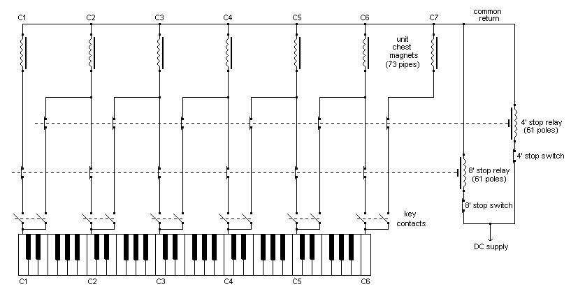
Figure 9. Unit chest control - deriving 8' and 4' stops from a single pipe rank
Taking a simple example, Figure 9 depicts a keyboard of five octaves (61 keys) and a six-octave unit chest on which 73 pipes are planted. Two stops, one at 8 foot pitch and the other at 4 foot, are derived from the single pipe rank. Each stop has its own switch controlling a separate 61-pole relay. Thus if the pipes are of diapason tone the stops might be labelled 'Open Diapason 8' and 'Principal 4'. The unit chest magnets are keyed via DPST key switches in the same way as before. Therefore the same enabling technology we have discussed so far (coupler relays and multiple key contacts) has now been employed to derive multiple pitches from a single rank of pipes planted on a unit chest. It is somewhat remarkable that identical electrical equipment can be used to control the two very different types of organ - those using slider chests and those using unit chests - and it illustrates the power and versatility of the economical system concept developed by Hope-Jones. Again, we take it for granted today, but that does not diminish the contribution he has made to the development of the organ. At the time he came up with these ideas they were genuinely epoch-making - Hope-Jones ushered in a new era of organ building
The brief description of unit chest control just given is all we need to apply the same ideas on as large a scale as desired - in principle you could build a complete theatre organ along these lines. In practice however, we need to discuss some additional engineering details first.
Drawing together all that has been said so far enables us to state a useful rule which governs the design of electromechanical actions:
The number of contacts operated by each key must equal the number of circuits controlled by it.
In other words, complete functional isolation between each and every circuit must be maintained. Otherwise we get problems due to unwanted currents flowing, sometimes in the reverse direction as well, giving rise to difficulties such as those described above in the context of a naively-designed octave coupler.
And what is meant by the term 'number of circuits'? In an organ using slider chests only (typified by Figures 5 and 8), the number of circuits per key equals the number of couplers sourced from the division in question plus one. A 'sourced' coupler is one whose current arises from (i.e. is sourced from) that division. Thus all intra-manual couplers on a division, such as sub and super octaves, count towards the number of circuits to be separately keyed. Inter-manual couplers count if a division sources (supplies) current to another one. Thus the Great organ sources current to the Swell to Great coupler and an additional key contact must therefore be provided, whereas no additional contacts are required on the Swell organ because the Swell to Great is not sourced from it (the Swell is the destination, not the source, for currents flowing through the Swell to Great coupler). By the same reasoning, the Great organ does not source the Great to Pedal - in this case the Pedal organ is the source division. Thus, in general, the source division of a coupler is that which is denoted last in its name - a coupler named conventionally as "X to Y" has a source department of Y. I have laboured this matter somewhat because it is important when drawing up circuits. It might appear complicated at first, but it's more intuitive than designing the system (which is actually a binary logic system) using Boolean algebra unless you are already familiar with it!
Having totted up the number of sourced couplers on a division, you then have to add one to the total to accommodate the chest magnet of the division itself. This then gives the number of circuits to be switched by each key on a division, and therefore the number of key contacts required.
The foregoing applied to organs using slider chests. In instruments using unit chests only (Figure 9) the number of circuits per key on a given division equals the number of speaking stops (NB not the number of ranks) on that division, plus sourced couplers if any. In Figure 9 there is one rank of pipes but two speaking stops for the manual division illustrated in the diagram. Therefore there must also be two contacts per key, as shown.
It follows from the above that the number of circuits to be switched at each key can sometimes become too large for the requisite number of contacts to be physically accommodated within the confines of a single key. Around ten contacts per key is a reasonable working limit using modern key contact assemblies of the type illustrated in Figure 7, though even this verges on the unmanageable. Although a switching capacity of up to 10 circuits per key will often be sufficient for 'straight' organs using slider chests, it is hopelessly inadequate for even the smallest theatre organs which of course use unit chests. For example, a small two manual six rank Style 'D' WurliTzer organ typically has 14 speaking stops on the Accompaniment division and 18 on the Solo. These figures exclude second touch stops, percussions, etc. It would be physically impossible to key this number of circuits directly at the key contacts. This would also have been true for some of the larger, fully unified, 'classical' extension organs which were common in the first half of the twentieth century. A 9-rank example by Compton [5] had 17 stops on the Great organ and 15 on the Positif. So what do we do when more contacts are required than can be accommodated at the keys? The answer is to use key relays.
By using a separate relay for each key, as many circuits as desired can be switched remotely (i.e. away from the confines of the keyboard itself) simply by providing the relay with sufficient contacts. At the same time each key now only has to operate a single relay coil, so it only needs a single contact. This greatly simplifies the console wiring. A further benefit is that the key relays can be remote from the console itself and placed closer to the coupler relays and pipe chests which they control. This is particularly advantageous when the console is detached because the number of wires in the interconnecting cable is vastly reduced. In the heyday of electromechanical actions the key and coupler relays with their somewhat fearsome interconnecting harnesses would commonly occupy a small room in unified organs of any size, and the whole assembly was often referred to as "the relay".
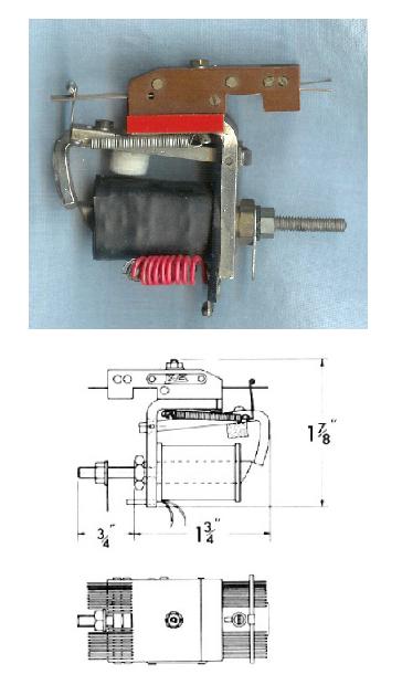
Key relays take many forms, with most organ builders having developed their own in-house designs. Wurlitzer used small electropneumatic relays whereas Compton preferred electromagnetic ones operated by lever magnets. An example of a commercially available relay which also uses a lever magnet is shown in Figure 10.
Figure 10. A relay capable of switching many circuits (courtesy Kimber-Allen UK Ltd)
Actually this relay (still available in early 2014) is sold for use in electromechanical combination actions rather than as a key relay, though it has nevertheless been used widely in the latter role. I have even seen them used for this purpose in some later Compton organs, though whether they were introduced at a later rebuild I could not say. However they were certainly available in the late 1950s at a time when Compton still existed as a firm.
Reliability, maintainability and robustness It is not straightforward to compare the reliability of electromechanical actions with electronic (solid state) transmissions such as diode keying or those using computer control because their failure modes are quite different. An electromechanical action contains hundreds if not thousands of contacts, and some of these will inevitably require attention (though often no more than cleaning) from time to time. On the other hand, electronic assemblies will typically prove entirely reliable for some, if not many, years but then they might fail completely and catastrophically. In these circumstances repair is seldom possible for several reasons, including their proprietary nature and the fact they can be at the mercy of rapid obsolescence over their lifetime. The necessary replacement costs will typically prove uneconomical and the situation can therefore result in an organ becoming useless. I have discussed the failure modes of electronic transmissions in detail in another article [6].
However, the fact that electromechanical actions are fundamentally simple enables them to be maintained or repaired by almost any organ builder, thus many examples have survived for well over half a century. Moreover, the fact they tend to fail gracefully rather than catastrophically is a decided bonus - an organist can usually continue to play when only the odd note fails now and again, whereas the sudden and complete failure of an electronic transmission is another matter. Many an organ built in the 1930s is still in working order because it has been properly maintained, which is one reason why electromechanical parts are still so widely available - there is still a market for them. In fact it is more likely that an action is replaced because modifications to the stop list are required, and this can be more difficult and expensive than replacing it. There is also the somewhat insidious temptation to replace something which is old simply because it is old!
There is no doubt that an electromechanical action is the most robust type. Typically it will survive all but the most damaging lightning strikes, which is definitely not the case for any form of action incorporating electronics.
Therefore it is suggested that churches and other owners of an organ with an electromechanical action think carefully before deciding to do away with it in favour of something more up to date.
Finally it should scarcely be necessary to mention that electromechanical actions will only survive and work well if proper attention was given to their electrical and mechanical aspects at both the design and implementation levels. Unfortunately this was not always so in the twentieth century, as my article in reference [7] pointed out.
This article has described how the electromechanical keying systems used in pipe organs since the time of Robert Hope-Jones in the 1890s were wired. There are still many such instruments around otherwise it would not be possible to obtain the action components today, therefore it is anticipated the article will address the needs of those who wish to maintain, repair or simply understand them. It was also the intention that the article might have some historical value. Circuits applicable to intra- and inter-divisional couplers were described, as well as those appropriate to organs using slider and unit chests. The extension principle was explained at the circuit level, together with some particular issues related to the fully unified organ such as the need for key relays. It was pointed out that well-designed electromechanical actions usually fail gracefully rather than catastrophically, they are readily maintainable, and they are more robust than their electronic counterparts against eventualities such as lightning damage.
Grateful thanks are due to Messrs Kimber-Allen UK Ltd for permission to reproduce the illustrations from their catalogue.
1. "Robert Hope-Jones - the evolution of his organ actions in Britain from 1889 to 1903", C E Pykett, 2010 (PDF download, 92 pages, 2.4 MB)
2. " ... the design of circuits requires great skill ... " (' The Organ', Peter Williams and Barbara Owen, Macmillan, London 1988).
Regrettably, having made a correct statement, these eminent authors then omitted to mention that the necessary skills were first honed by Robert Hope-Jones. Indeed, elsewhere they pull no punches in jumping onto that bandwagon overcrowded with his detractors (e.g. Hope-Jones built " ... the worst organs ever made ... "; they " ... are considered the worst in organ design ... "; &c, &c). Er - can this really be 'scholarship'? Hopefully this article will provide material which objective readers can use to make up their own minds on the matter.
3. A bar and slider chest (or slider chest for short) is one having a single pallet valve for each key which can admit wind to some or all of the pipes corresponding to the same note on the keyboard, depending on which stops are drawn. For the purposes of this article the important point is that only one electric action (direct electric or electropneumatic) is required per key or pallet, regardless of how many pipes are controlled by it. This differs from an organ using unit chests in which each pipe has its own electric action. The two types of chest result in quite different engineering architectures as far as their actions are concerned.
4. “Electrical Aid to the Organist”, R Hope-Jones, Proceedings of the College of Organists, 5 May 1891.
I have discussed this lecture in detail in another article on this website (Hope-Jones at the College of Organists). Although it demonstrated beyond doubt the power of Hope-Jones's fertile mind as a visionary engineer, it also revealed some of his less attractive personality traits which I did not hesitate to draw out in this critique. One must differentiate between the man and his work, rather than allowing the two to intermingle unhelpfully. I think this is a trap which so many commentators on Hope-Jones have allowed themselves to fall into.
5. "The Organ", W L Sumner, 3rd edition 1962, Macdonald, London, p. 434.
6. "Reliability and Obsolescence in Electronics", an article on this website, C E Pykett, 2010.
7. "The Evolution of Electric Actions", an article on this website, C E Pykett, 2005.
|