


|
|
|
Reliability and Obsolescence in Electronics
by Colin Pykett
Posted: 6 July 2010 Last revised: 19 January 2011 Copyright © C E Pykett
Abstract. Complex electronics is employed frequently in pipe organ actions as well as in digital organs, and if it fails the entire instrument becomes useless. This is particularly catastrophic for pipe organs in view of their cost. Written largely at a non-technical level, this article shows that it is probably realistic to expect the consumer grade electronics used for both types of instrument to have a lifetime up to about 20 years. Although this might sometimes be exceeded, it is the case that too many examples exist where failure occurred earlier. The malfunctions are explained by referring to the reliability and failure modes of components including transistors, integrated circuits, passive components, power supplies, soldered joints, contacts and connectors. The failures contribute to premature obsolescence because it is frequently the case that repair is either uneconomic or impossible owing to the unavailability of key components which themselves have become obsolete. The upshot is that replacement, rather than repair, of the failed electronics will be necessary at a typical five-figure cost in pounds sterling if an otherwise good pipe organ is not to remain silent. A digital organ of the same age would probably be summarily scrapped and replaced by a new one, and a similar figure would likely be involved in many cases.
The fundamental incompatibility between the long life expected of a pipe organ and that of the electronics many of them contain will be noted. In the case of digital organs, regular replacement of the entire instrument seems an inescapable consequence of the decision to purchase one in the first place. Because the issues addressed apply to both pipe and digital organs, this article appears under both headings on the Complete Articles index page on this website.
Contents (click on the section headings below to access them)
Electronic products come in two varieties. A minority includes those which must work reliably and for an indefinitely long period in satellites, aviation and other aerospace systems, and in some military applications. These are characterised by very high up-front costs, and the incorporation of customised components of high reliability which must continue to be available for many years or even decades. The husbandry aspects alone of the latter aspect underlie a specialised business in its own right. Few outside the aerospace and military electronics sectors come across these products. By far the majority of the products we encounter in everyday life are examples of so-called consumer electronics, characterised by cheapness deriving from components of sometimes inferior quality, sometimes poor build standards and enormous production volumes. There is also a tendency towards rapid obsolescence which in some cases is deliberately built into the products. Attempts by consumers to overcome obsolescence by striving to keep items working beyond a few years can be frustrated by the unavailability of key components and uneconomic repair costs.
There is almost nothing occupying the middle ground between these two extremes. Thus for obvious reasons the electronics incorporated in digital organs, and in pipe organs using electronic control systems in their actions, must perforce fall into the consumer electronics category because they must use components developed for the mass consumer market. But herein lies a fundamental problem. Pipe organs are expected to have a very long life, a century being a not unreasonable goal given regular maintenance. This goal was met frequently by many mechanical action organs built up to the end of the nineteenth century, which explains why we still have so many of them in British churches, and it has set the standard of dignified longevity which we have come to expect of a pipe organ. This expectation remains reasonable and justified today, if only because of their cost. But if a pipe organ incorporates consumer electronics in its action, a trend which began in the 1960’s and has accelerated ever since, there is obviously a fundamental incompatibility. There are too many examples of organs which have become silent because the consumer grade electronics gave up before the rest of the instrument, as it almost inevitably will, and I have discussed these matters in detail elsewhere ([1], [2]). One recent example is that at the important city centre church of St Peter in Nottingham where the electronic transmission system failed during a service, and replacement was deemed uneconomic. The consequence was that the church decided that repair or renovation of the existing instrument was not feasible, and (as of August 2010) it is to be replaced with a hybrid pipe/digital organ [3]. This led a Consistory Court in another Diocese to suggest that such instruments might be no more than risky and potentially expensive experiments, though they appeared to have misunderstood the situation at St Peter's [4].
Digital organs are much cheaper than pipe organs of course, and they too use consumer grade electronics, so they can and must be replaced more frequently. However a concomitant advantage is that digital music technology advances so quickly that the replacement also brings with it an improvement in the way the instruments sound. But the intimate mating of pipes with electronics in recent hybrid organs, such as that proposed for St Peter’s, means that the entire instrument becomes unusable if the electronics fail. In this respect they are just as technically fragile and vulnerable to failure as pipe-only organs with electronic control systems have been over the last fifty years.
The remainder of this article examines in more detail several aspects of consumer electronics so that its short life, and the failure modes responsible for it, can be better understood. Only hardware aspects are considered here, though it should be remembered that all current systems also rely heavily on embedded software (computer programs). The latter has a set of problems of its own, but these will not be considered here to keep the scope of the article within reasonable bounds. Because the issues addressed apply to both pipe and digital organs, this article appears under both headings on the Complete Articles index page on this website. Perhaps unsurprisingly, the appearance of the article prompted an immediate defensive response from some in the organ business. One such, who also contributes frequently to Internet discussion lists, wrote publicly only a month later "read it and weep. Your 20 year old wunder [sic] appliance will shortly go down the river". However he also started a correspondence during which it transpired there was little between our positions - among other things he conceded privately that obsolescence was indeed a major problem contributing to the limited lifetime of electronics.
Analogue and digital circuits are actually the same thing! "Garbage", I hear you cry. But there is some truth in the saying that all electronic circuits are basically analogue. What is actually meant is that the fundamental laws first developed in the nineteenth century, and subsequently used for analogue circuit design, are the same regardless of whether the circuits are digital or analogue. These laws describe how circuits work in terms of voltages and currents, and examples are Ohm’s Law, Kirchoff’s Laws, etc. What distinguishes the two types of circuit is merely the meaning of the signals within it to us human beings, though the circuit itself does not of course ‘know’ anything about this because it is a philosophical, semantic issue. Therefore, whether digital or analogue, it is nevertheless just a circuit in which the voltages and currents are at all times related by Ohm’s Law etc. Thus the voltages and currents in an analogue circuit have definite values, and these values have some meaning or other to the designer at all instants. However in a digital one, they are quantised in amplitude (i.e. they can only adopt discrete values) and they are also sampled (chopped up) in time. Therefore they only have meaning to the designer at the sampling instants and if they possess certain amplitudes (logical 0 or 1). But the way the voltages and currents actually change between the 0 and 1 levels in the gaps between successive sampling instants are still governed by the basic laws of circuit theory, even though the values have no meaning while they are in the process of changing.
It follows that matters of reliability are governed by similar rules for both analogue and digital circuits. Electronic devices are temperature sensitive, for instance. Taking an example from the analogue domain, the output transistors in an audio amplifier must not get too hot otherwise they will fail. This is why Class A amplifiers, in which the full power supply current flows continuously through the transistors regardless of the signal level, are so rare because they cannot deliver the high output powers usually demanded since they would get far too hot. Class AB or Class B output stages, although inferior in terms of distortion, are usually used instead, in which the current is instead related to the instantaneous signal level. A digital example is the processor chip such as a Pentium or Celeron in a PC, which often requires annoyingly noisy fans to keep it cool. Here, much of the heat arises from the passage of current through the microscopic conductors within the integrated circuit package, and the waste power dissipated as heat can be calculated by Ohm’s Law just as it can for a simple resistor in analogue circuits. In the digital case, by far the majority of the heat generated is during the transitions between logical 0 and 1 states, rapid though they are. While the voltage in a conductor is sitting at a 0 or 1 level, appreciable heat is not generated because virtually no current flows owing to the properties of the CMOS transistor circuitry used. Appreciable current is only drawn by a CMOS transistor circuit during the transitions between 0 and 1 or vice versa. Therefore the heat generated by a digital circuit is largely that corresponding to the meaningless information it generates as an inescapable consequence of its operation!
Digital organs contain more components than most other items of equipment likely to be found in the home or sometimes in the workplace. It is reasonably obvious that the more components a piece of equipment contains, the more one has to pay attention to reliability. Those readers who are familiar with formal quality assurance (QA) techniques will know that there are well-defined procedures for working out how reliable a system will be in terms of statistics such as mean time between failures (MTBF), and these are related directly to the number and type of components used. This article will not dwell on reliability at this formal level but will instead discuss some of the common problems I have encountered during a lifetime of electronic design and construction, both professionally and at home. In any case, formal QA tends to be rather pessimistic, as was found during the second world war when some huge electronic contrivances were hastily thrown together. One of these was ENIAC, one of the earliest US computers which used 18,000 thermionic valves (vacuum tubes) as well as vast numbers of passive components and relays. Colossus was a British computer built (and now rebuilt) on a similar scale for use in code breaking at Bletchley Park. Fortunately, in both cases it was found that the doom laden predictions of the QA people were confounded provided the machines were left switched on all the time, enabling the weaker components to be weeded out in the first few hours or days. Even so, the average continuous error-free operating time of these and similar machines was only around 30 hours.
Today the average digital organ, or electronic pipe organ transmission system, contains much larger numbers of components than these early machines, mainly because of the untold millions of transistors and their interconnections hidden inside the integrated circuits. Also there can be few pieces of equipment with as many of those potentially unreliable components, contacts and connectors, as organs of either type. So the reliability of both pipe and digital organs are of paramount importance, as many organists will know to their cost! The following sections of the article consider some of these reliability aspects in more detail.
It is commonly assumed that transistors have an indefinitely long life, so it can come as a surprise when they or the integrated circuits (IC’s) made up from them fail suddenly. In fact all semiconductor junctions as used in transistors have a finite life for a number of reasons. Temperature has already been mentioned and it will now be discussed in more depth. The hotter a junction runs the shorter is its life, since lifetime halves for every temperature increase of 15 degrees or so. Any silicon transistor or IC which runs at over 80 degrees Celsius will fail in a time which can be embarrassingly short, and even at lower temperatures lifespan can be limited. I have a hi-fi amplifier about 40 years old which I have continued to maintain as a test bed to monitor and confirm how consumer electronic circuits fail over periods longer than their design life. Over this time span I have had to replace the output transistors in both channels. The output stages operate in class AB, which means that a quiescent current is always flowing through the transistors even when no audio signals are present. Thus the transistors reach a temperature which is uncomfortable to touch (around 60 degrees) after half an hour or so, and this anecdote confirms the sensitivity of semiconductor junction lifetime to temperature.
I also have a quite expensive CD player which produces distorted sound, but only in the summer (I am not joking!). I think the most significant bit drops out at higher temperatures, producing awful distortion on the loudest passages. The manufacturers have had it back under warranty but have not fixed it. This anecdote demonstrates two things: firstly that the temperature does not have to be all that high before things start to go wrong (there is nothing inside the CD player which runs particularly hot), and secondly that digital as well as analogue systems suffer similar problems from time to time. The first point, that the temperature need not be excessive, needs to be borne in mind constantly when dealing with complex IC’s designed for the consumer market. Sometimes their maximum operating temperature limit is only around 25 degrees, which indeed may explain the problem with my CD player. If you look carefully through the specification sheets for complex consumer IC’s, you will find the same limit sometimes applies to others. As another example, I have an electronic organ in which one or two such ICs sometimes stop working a short time after it has been switched on – but, again, only in summer! There are ways in which one can overcome it, such as by slightly increasing the power supply voltage, but this is rather crude. The conventional way of keeping equipment cool with a fan is not easily applicable to organs, or indeed CD players, because of the noise problem. (And if you are driven to using a fan, you might as well consider a pipe organ).
Another reason why transistors or ICs fail is the imperfect hermetic seal afforded by cheap commercial grade plastic packages (Figure 1). Over time moisture or atmospheric gases can get inside and poison the semiconductor junctions, which are made of silicon and other elements of exceptionally high purity. The hotter they run, the quicker this happens. This is one reason why military-specification devices are housed in ceramic packages, but these are vastly more expensive to manufacture.
Figure 1. Consumer grade transistor in a plastic package
The symptoms of semiconductor junction failure, whatever the reasons, are often slow in onset and inexplicably intermittent. This was true of my hi-fi amplifier transistor failures, and I have also observed it with some ICs. But junctions can also be damaged at equipment switch-on or switch-off, and this will now be discussed.
It is not easy to predict what will happen to a circuit when the power is turned on or off. Although such analyses are undertaken for aerospace and military electronics, the process is expensive and it requires engineers with specialist expertise. Therefore the problem is largely ignored for consumer electronics, so it is difficult to know where to start the discussion here. One way to begin is to realise that so-called stabilised power supplies often have a relatively long time constant when responding to mains voltage or load variations. This is because they sometimes use low bandwidth sense amplifiers (such as the 741 operational amplifier which has an open loop bandwidth of only 30 Hz) in the stabilisation circuit. Thus at switch-on, the voltage provided by the supply may transiently overshoot its design value before the stabilisation circuit can catch up. This can be bad for the components in the circuit being fed by the power supply, and although they may survive for some years, this can nevertheless be one of the insidious failure modes of the system. The absolute maximum rating of some digital IC's operating from a nominal 5 volt power rail is very little above the 5 volts, particularly for consumer IC's. If the survival of an elaborate or expensive circuit depends on the power supply behaving itself, then fast acting over-voltage limiters or surge suppressors should be placed across the power supply outputs. They should be chosen to have a breakdown voltage only a volt or so above the nominal power rail voltage. This measure will also provide some protection to the circuit in the event of catastrophic failure of the power supply.
Another switch-on problem can occur with dual power supplies intended to provide plus and minus 12 volts or similar. Usually the risetime of the two halves of the supply when it is switched on will not be anything like identical, mainly owing to the tolerances of the electrolytic smoothing capacitors, or because of uneven current loading of the two halves by the circuit to which they are connected. This also can be bad for electronic circuitry, because a common failure mode can be due to excessive base-emitter current flowing in a transistor before the collector potential has stabilised. For example, this can happen transiently to an NPN transistor if the negative rail comes up faster than the positive one. In other words, a transistor whose collector voltage is not high enough does not exhibit transistor action at all, and in these circumstances its base-emitter junction is simply a forward biased diode. Excessive current through this fragile junction (not designed for power dissipation like the collector junction is) will destroy it. Again, remember that everything that has been said for the individual junctions in a discrete transistor also apply to those in IC's. If power supply transients are not to be a problem, the most elaborate precautions have to be taken such as first allowing the power supply to stabilise before it is applied to the circuit in a controlled manner.
Figure 2. Small resistor (1000 ohms, 0.25 watts)
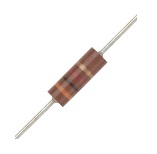
Passive components tend to get overlooked when problems arise. If you see a resistor (Figure 2) on a circuit board, how often do you consider whether it is behaving itself? In fact, generally they go high in value with age. The higher the ohmic value, the worse this problem seems to be, and it also seems to depend on the power they are dissipating. A common manifestation of the problem is the neon mains indicator lamp on, say, a freezer which gradually gets dimmer before it goes out completely. One's inclination is to suspect the lamp itself, but the associated resistor is usually just a tiny quarter-watt 1 megohm resistor which dies of old age before the lamp fails. Similar things can happen to any resistor in any circuit.
Preset resistors inside equipment and potentiometer controls which are operated by the user are frequently extremely unreliable. The contact resistance between the wiper and the track varies over its travel, and whatever problems exist will worsen with age. Also the ohmic value of the track itself will almost always go high over time, particularly in the cheaper varieties. Problems can also arise at the points where the track ends are connected to the solder tags, usually by rivets. Either these loosen as the preset is adjusted, as corrosion is set up, or the metallised areas under the rivet heads seem to become highly resistive.
All the above problems are made worse if direct current passes through a composition (as opposed to wire wound) variable resistor, and circuits should be designed so this never happens. If it occurs with a variable resistor used as a gain or tone control, it is largely responsible for the premature appearance of noise when the control is operated. In my old hi-fi amplifier already referred to, all the controls had to be replaced for this reason after only a few years of service.
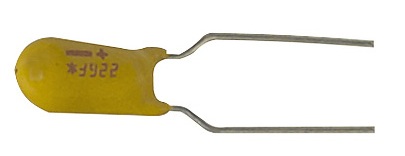
Figure 3. Small tantalum electrolytic capacitor
Capacitors are also liable to unreliability. Failures include catastrophes such as an exploding aluminium electrolytic capacitor in a power supply, which can be dangerous in view of the stored energy if you happen to be in the way at the time. I once had direct experience of this in a power supply in which the offending electrolytic was near to a rather hot resistor. Clearly they dislike heat, and it is important to operate components such as these within the manufacturer's environmental specification just as much as within the electrical one. In fact aluminium electrolytics have very short lifetimes at quite moderate temperatures - these are the small cans one sees sprinkled liberally over almost any printed circuit board nowadays. As I write this I am looking at a recent (May 2009) data sheet which quotes a "very long and useful life: 2500 h to 6000 h". 6000 hours? That's barely over eight months! This lifetime figure refers to operation around the boiling point of water, a value often approached within the closely-confined spaces of today's miniaturised electronic assemblies. Despite this potential problem which ought to be well known to professional engineers, it is notable how many electrolytic capacitors seem to cluster around the hot heatsinks of consumer-grade electronic items such as computer motherboards, which is the worst possible location for them. As a specific example, I once repaired a flat screen monitor which had two of these items mounted only millimetres above a very hot heatsink, so hot that nearby soldered joints had failed. Not surprisingly, it had given up after only a few years' service. One is entitled to draw one of only two conclusions in such situations - either the designers of such assemblies are appallingly incompetent, or the manufacturers have an unbelievably cynical approach to the encouragement of rapid failure.
Moving on, any type of capacitor can inexplicably go open circuit. But the failure I have come across most frequently is with small tantalum electrolytics (Figure 3) developing a short circuit. In all cases they were working well within their voltage limit, and I can only assume that over a period of some years they failed because of transient over-voltage or reverse-voltage surges at switch on or switch off - power supply problems again. Failure of tantalum capacitors has happened in my elderly hi-fi amplifier already mentioned, in an electronic organ (several in that case), and in a commercial low voltage action power supply for a pipe organ. In the latter case, the capacitor in question was shunted across the output, resulting in dire consequences when it failed.
Soldered joints are ‘dry’ when the solder does not combine properly with the metals it is intended to unite. This can happen as a result of faulty construction (which is therefore a quality control failure), or it can arise during operation. To an expert eye a dry joint is usually identifiable on visual inspection, though this is more difficult today owing to the use of lead-free solders which can endow a grey crystalline appearance even to sound joints. Most dry joints cause problems which can be difficult to track down because the associated symptoms are often intermittent. One of the worst examples of this type of problem I have encountered was a joint in an electronic organ which gave no trouble until twelve years after the assembly was manufactured, seemingly due to fatigue. It eventually gave rise to a fault which resulted in 16 foot pedal notes on bottom F sharp causing distortion. After much fruitless searching and head-scratching a joint was eventually found which was sensitive to this frequency, probably because it was located at an antinode of the high-amplitude associated standing wave in the room in which the organ was installed. At other frequencies the antinode occurred elsewhere inside the console and so did not vibrate the component soldered to this particular joint. Over the years it is probable that the vibration had loosened the joint due to metal fatigue.
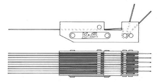
Soldered joints should never be subjected to movement, especially frequent movement. Key contacts which are soldered directly to tags or printed circuit boards will, quite simply, always fail. Of course, it is necessary to solder to key contacts, so what does one do? It is essential to mechanically isolate the soldered joint from the movement of the contact wire, as is done in the design of proper contact blocks (Figure 4). However some of the cheaper digital organs keep the price down by using inferior contact assemblies, and they are therefore prone to suffer from this defect.
Figure 4. Typical organ key contact assembly (courtesy Kimber-Allen UK Ltd)
Most organs, both pipe and digital, contain hundreds of contacts and they cause myriads of problems quite apart from dry joints, some of them obvious but others being more subtle. Among other things, it is necessary to appreciate the pros and cons of the various metals before deciding on the material to use.
Because it is chemically unreactive and therefore does not corrode or become contaminated by atmospheric gases, gold is the most suitable metal for switching low level electronic signals. But because of its cost so-called ‘gold’ wire is in fact only gold-clad, so this material should not be used where arcing is likely to occur as this will cause the gold to burn away. Even tiny amounts of arcing will cause problems over time, such as in keying systems where a capacitor is charged or discharged through the contact wire. Inductive loads such as relays should never be switched by gold contacts even if suppressor diodes are fitted across the coil. The same applies to incandescent (tungsten filament) lamps, which take a high transient peak current until they reach their operating temperature.
Silver is not always a satisfactory material to use for contact applications. Its popularity probably stems from a belief that, because it is the best metallic conductor of electricity in terms of conductivity, then it must therefore be good for use in contacts. But its disadvantages, including cost, are significant. Electrically, its main disadvantages stem from the fact that it is highly reactive. In the atmosphere it rapidly tarnishes and turns black. This results in an apparently little-known nonlinear electrochemical effect which makes the switching of voltages below about 6 volts unreliable, whereas there is less of a problem at higher potentials. Professional electronics engineers should be aware of this as it affects the choice of a relay for example, though some organ builders nevertheless use silver for switching 'logic' signals at 5 volts and thereby invite unreliability. The problem tends to be worse if gas heating or cooking is used in the same building as the organ; this increases the sulphur level of the environment and tarnishes silver even more quickly. A wiping contact action will not be effective in combating tarnish.
Another problem with silver is its relatively low melting point. Therefore arcing causes silver contacts to fail, either through contacts welding together (which can also happen with relays) or it can actually burn through the wire. Electric action pipe organs which have suffered from this defect, with many contact wires broken off, are not unusual.
Much of what has been said about materials for contacts applies to the pins and sockets of connectors. Gold is used in the best quality items and it will be generally reliable. Silver appears to be used less frequently than it once was, perhaps because designers are becoming more aware of its shortcomings. Tin plated connectors seem to be remarkably reliable considering their low cost, though perhaps not in less benign atmospheric environments, but beware of very cheap items because some of them are only designed for a maximum of 15 or so separations. Reputable suppliers will specify this.
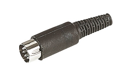
DIN plugs and sockets seem to be a prime example of euro-bureaucracy. The DIN system generally is far too heavy on paper specifications and far too low on delivering performance. As an example, take the so-called DIN loudspeaker plugs and sockets which in no way are suitable to cope with the high currents involved (peaks of many ampères are not unusual, especially with the pedal notes on digital organs). In fact they are so flimsy they can barely hold themselves together without the plug falling out under the weight of the connecting cable. Then the build standard of all DIN components has to be scrutinised carefully before use - often there is a solder bucket riveted to the ground pin which one might think is convenient when wiring the connector. But how often is it found to be loose, or becomes loose in service? If you think DIN connectors are passing out of fashion in electronics, remember that they are still widely used in the MIDI systems found in both pipe and digital organs, where their use is mandated by the MIDI specification itself (Figure 5).
Figure 5. 5 pin DIN plug as used for MIDI connections
Ready made leads with connectors moulded onto the ends are popular in consumer electronics, but again you have to be prepared for shoddy workmanship which cannot be detected easily because the connectors cannot be dismantled. Dry joints are a common problem. I once had a situation in which mains hum sometimes appeared after an amplifier had been switched on for a while, and it gradually increased in loudness until it obliterated everything. It turned out to be a dry joint on the ground pin of one of the moulded connectors (a DIN plug as it happened!). When the connector was cool at switch-on everything was well. But as the amplifier got warm the plastic moulding material became softer and the dry joint moved apart. It took months to sort this problem out.
When assembling multiway plugs and sockets, it is necessary that the wiring does not constrain the free movement of the pins and receptacles. Usually this is designed in deliberately, and poor contact can occur in some lines if each one cannot move to take up its optimum position when the connector is mated. On the other hand, this free movement can also be a cause of failure because of the fatigue stress set up on the soldered joints when the pins move. This is one reason why crimped connections are more reliable, particularly for connectors which are taken apart frequently.
Obsolescence has already been touched on and it will now be addressed in more detail in view of its importance to the subject matter of this article. Consumer electronics is characterised by rapid obsolescence to the extent that a life of more than about six years is not expected. This figure is apparently reflected in consumer legislation in the UK in that an item which lasts for significantly less than this period can be considered to be not of merchantable quality, and case law suggests there is a reasonable probability of a successful outcome if tested in court. To prevent a case being brought, retailers or manufacturers will therefore sometimes offer some form of compensation if one is sufficiently persistent, though they do not usually concede it as a matter of course and until the customer has jumped several hurdles. Beyond six years however, the prospect of redress becomes remote.
Among other things, product lifetime is defined by obsolescence due to essential components such as special IC’s not being available at the time of repair, and this can be deliberate policy on the part of a manufacturer. Another factor is the often uneconomic repair costs even if the parts are available. The upshot is that it is often cheaper to throw away and buy new, and although it is peripheral to the thrust of this article, the e-waste problem thus created is significant. For example, much electronic equipment contains highly toxic material such as beryllium or lithium, requiring specialist recycling which is seldom carried out even in developed countries.
On this basis, one might expect that the consumer grade electronics incorporated in pipe organ control systems or in digital organs would also not last for more than six years on average, though it is probably fair to say that this conclusion would be pessimistic. The six year figure relates more to computers, audio-visual equipment, games consoles and the like, all of which are bought in enormous quantities. As well as the manufacturers, consumers of these products are themselves partly responsible for their short lifetime because of an apparently insatiable demand for updates or the latest technology. The situation for the much smaller and more specialist market for electronics incorporated in pipe and digital organs is rather different and therefore it requires more careful examination.
Although there are indeed too many cases of unacceptably short lifetimes of the type of electronics we are concerned with here ([1], [2], [3]), there are also examples at the other end of the scale. A number of manufacturers of digital organs, for instance, undertake to keep any instrument they have ever made in working order. Whether the cost involved would always be acceptable to the customer is another matter though. To illustrate the situation with a specific example, many digital organs made in the early 1990’s used the M114 wavetable synthesiser chip. This became obsolete long ago but it can nevertheless still be obtained fairly readily from a number of sources, either in the form of new old stock or second hand (i.e. recovered from old instruments). However the cost of such obsolete parts today is usually significant and it might be prohibitive were many required, perhaps if the instrument in question had been damaged by a power supply failure, lightning strike or similar catastrophe. Issues such as these have resulted in typical installed lifetimes for electronic organs in churches varying between 10 and 25 years, figures which were quoted by the Institute of British Organ Building (IBO) when they last published them in 2006 [5]. Although only four instruments were represented in this particular survey, the implied average lifetime of around 17 years was nevertheless compatible with previous data published both by the IBO and others.
It is unfortunate that the IBO seems not to have published comparable data for the lifetimes of pipe organs before major repair or replacement becomes necessary, nor in particular for the electronic modules incorporated in them which are the subject of this article. As to cost, that of replacing failed electronics in pipe organs is broadly comparable to replacing a digital organ in the medium price bracket. As examples, the failed electronic transmission in the organ at St Peter’s Nottingham which was mentioned earlier lasted for 24 years and would have cost at least £10,000 to replace [3], and that for the rebuilt organ at All Saint’s, Margaret Street in London ran to £20,000 in 2000 [6].
This article has surveyed some of the major hardware failure modes of the consumer grade electronic modules employed both in pipe organ actions and in digital organs. These contribute to relatively early obsolescence in that essential parts such as integrated circuits often become unavailable after a few years. Thus an expected lifetime of the electronics in pipe organs and digital organs will not often exceed 20 years or so in round figures. Although some will fail more rapidly and others will last for longer, it seems reasonable to adopt a 20 year life as an average working assumption. Repair of consumer grade electronics of this age is likely to be uneconomic at best and impossible at worst, which means that replacement of the electronics will be necessary at a typical five-figure cost in pounds sterling if an otherwise good pipe organ is not to remain silent. A digital organ of this age would probably be summarily scrapped and replaced by a new one, and a similar figure would likely be involved in many cases.
The fundamental incompatibility between the long life expected of a pipe organ and that of the electronics many of them contain will be noted. In the case of digital organs, regular replacement of the entire instrument seems an inescapable consequence of the decision to purchase one in the first place.
Thanks are due to Kimber-Allen UK Ltd for permission to use the illustrations of their key contact assembly.
1. "Electronic Transmission Systems", Organists’ Review, C E Pykett, August 1999.
2. "The Evolution of Electric Actions", C E Pykett, 2005.
3. "Replacing the organ, St Peter’s Church Nottingham", web article, Peter Siepmann, 10 January 2009.
4. "Hybrid may replace pipe organ, despite DAC view", Shiranikha Herbert, Church Times, 30 April 2010
5. "Review of the year", Ian Bell, Organ Building, volume 6, Institute of British Organ Building, 2006.
6. "All Saints Margaret Street London W1 Organ Restoration Appeal", church pamphlet c. January 2000.
|