


|
|
|
ELECTRONIC
TRANSMISSION SYSTEMS
by Colin Pykett
Published in Organists' Review: August 1999 This version last revised: 22 December 2009 Copyright © C E Pykett
"You roll back the stones, and you find slithering things" Adlai Stevenson
* This commissioned article first appeared in Organists' Review in August 1999, and it is now reproduced here because of the number of requests received for reprints. In this version of the article I have included some pictures and diagrams which did not form part of the original.
On the whole it was well received, although there were a few in the trade who obviously found the turning over of this particular stone rather uncomfortable. As an example, a prominent organ adviser (a member of the AIOA) wrote that " ... the moral here is not to argue for or against the professionals unless you are sure of the facts ... ". Quite which bunch of professionals he had in mind mystified me, particularly as neither he nor anyone else raised a single point relating to the factual matter of the piece. He went on to relate that a certain Mr X of firm Y (a supplier of solid state organ transmissions) had complained to him that the article had "damaged his business", though the fact that Mr X felt it necessary to hide within the skirts of an organ adviser while making this allegation tells its own story. Previously I had assumed, obviously naively, that a consultant of his stature would have been less cosily associated with the trade, or at least less inclined to reveal the fact. He also objected that some of his clients had queried his advice after the article appeared, as though the punters shouldn't be encouraged to ask questions. Other aspects of his discourse revealed him as a master of argumentum ad personam, incapable of conducting an objective and civilised dialogue. This sort of response, of course, showed that the article had achieved its aims.
*
Abstract This article surveys
the advantages and disadvantages of electronic (solid state or multiplex)
transmissions used in organs with electric action to communicate between the
console and the pipes. Such
transmissions are mandatory in the relatively few cases where the console must
be often moved or disconnected. But in this and other cases it is shown that the
other potential advantages of relative cheapness and increased reliability may
be offset by a number of disadvantages peculiar to electronics.
These include some examples of spectacular failures, obsolescence and
difficulties caused by scanning delays. Also,
musically speaking, the use of electronic transmission puts
pipe organs into the same category as electronic organs as far as control by the
performer is concerned. The article
suggests that the traditional, non-electronic, approach to electric actions
might be looked at more carefully particularly if an old action is being
renovated, and some suggestions for refurbishing old electric actions are given.
Colin
Pykett is a physicist who has retained a life-long interest in organ design and
construction, mainly because he plays the instrument and has struggled to
reconcile its technology with its music. The
encroachment of electronics into organ building is not entirely happy, and for
this reason he was grateful for the invitation to contribute this article.
Introduction This is a commissioned article. It arose from the correspondence which followed the publication of my article on electronic organs (reference 1), in which interest was expressed in the keyboard scanning systems employed in such instruments. Since similar systems are also used in pipe organs, various people subsequently called for a description and assessment of this method for controlling organs with electric action. Before proceeding further it may be useful to summarise the applications for electronics in modern organs. Firstly there is the increasingly common use of electronic (also called solid state or multiplex) transmission, which is the main subject of this article. Secondly, electronic or solid state relays are sometimes used for a number of purposes in actions which do not necessarily use electronic transmission. For example they may be used to control the heavy currents demanded by direct electric action magnets; these could not be switched directly by the key contacts. Or couplers and reverser units might use electronic rather than electromagnetic relays. Thirdly, electronics appears in combination capture systems, sequencers and the like. As with electronic relays, these can exist independently of electronic transmission and indeed they are often found on mechanical action instruments. Some comments on these latter systems are made in the postscript to this article. Somewhat regrettably, I have found it impossible to avoid going into some technical detail. For the article to be useful as a reference source, it was necessary to include some definitions of terms particularly those associated with the technical background to the MIDI system. However it should be possible to speed-read the article without getting hung up on these aspects. Before diving into the detail, however, it is appropriate to look at the historical background which has given rise to electronic transmission. Historical background Detached consoles have been around for a long time, and it is not all that unusual to find them even in old organs using mechanical action. During the last century they became more popular with the advent of pneumatic actions, but in neither of these cases was the console moveable. This only became possible with electro-pneumatic actions towards the close of the nineteenth century, since the entire connection between console and organ could then be contained within a flexible multi-wire cable having a diameter of around an inch. There then arose a veritable epidemic of detachment, epitomised by the photograph of Robert Hope-Jones at the console of the organ in St John’s Birkenhead. Apparently that console could even be moved outside the church and out of earshot of the pipes, provoking W L Sumner (no admirer of Hope-Jones) to remark that if the organ was a good one such a feat would be unnecessary. Presumably the same comment applies to the performer.
Robert Hope-Jones playing his celebrated organ at St John's, Birkenhead, from outside the church c. 1890. The organ was probably in its final form by 1889 having been transformed by Hope-Jones and Franklyn Lloyd over several years, assisted by various members of the choir and some colleagues from Hope-Jones's day job at a telephone company. Much of the work was done in the evenings in nearby rented premises. Note the cable snaking its way into the gloom within. It was some 50 yards long and contained 343 wires, though today's electronic transmission techniques could reduce this to just 2. The reason why he chose to wear a mortar board, and which institution had granted it to him, are questions for which I do not have the answers. Some of the wording on the notice board is readable, confirming that this version of the photograph has been printed the correct way round - some others are a mirror image.
These early actions made increasing use of the relay technology which had originally been developed for telegraphy around the middle of the nineteenth century. That technology became more sophisticated with the development of telephony in the 1890’s, and a key figure in both this and the organ field was Hope-Jones. It was primarily he who realised that multi-contact relays derived from those used in telephone exchanges could be used to provide couplers and other devices in profusion, and he embedded them as part of the tonal design strategy which is today associated with him. He also applied such relays to the control of the unit chests which are essential to the extension organ. As these techniques became more widespread organ builders often made up their own relay gear from basic components until high quality coupler relays and the like became widely available from supply houses in the 1950’s. Compton’s, for example, used a paxolin “trace” (a lightweight perforated insulated strip) to pull in large numbers of contact wires towards busbars under the control of a single electromagnet in both their pipe and electronic organs. However, many relays of this vintage suffered from unreliability due to oxidisation of the contacts, in some cases because unsuitable contact materials had been chosen. There were also other reasons for the unreliabilities. Relay design is a sophisticated art which is not apparent from the simple principles involved, and home-made relays are seldom effective over a long period of operation. Unreliability was one reason which has led within the last 20 years or so to a further revolution in the way electric action organs are controlled. Electronics has entered the scene, and nowadays it is common to find that the connection between console and organ is a thin coaxial or fibre optic cable. This is connected to a box of electronics at each end. Taking a simplified view, a coaxial cable is electrically similar to just a pair of single wires and it sometimes bemuses people as to how this can carry the same information as the old fashioned multicore cable. The fact that electronics is used at each end of the cable gives rise to the term electronic transmission. In an electronic transmission the need for cumbersome coupler relays, indeed relays of any sort, is done away with. An
equivalent term is solid state
transmission, arising because of the use of so-called solid-state devices
such as transistors and the integrated circuits made up from them.
In the 1950’s the transistor was beginning to rapidly oust the valve (thermionic
vacuum tube) as the work horse of electronics, and the term solid-state was
attached to this device because it arose from research done in the field of
solid-state physics (the physics of solid semiconductors such as silicon and
germanium) in the 1940’s. Yet
another term describing these recent systems is multiplex transmission for reasons which will be described later. Advantages of electronic transmission What are the advantages of electronic transmission? Firstly it is evident that there ought to be a cost saving, not only in the replacement of many individual long copper wires by a piece of coaxial cable, but in the labour involved in constructing the system. Gone are the looms of multiple wires inside the console and organ, painstakingly laced together by generations of apprentices and soldered at each end to hundreds of contacts. Also it was difficult to physically disconnect the console from the old multicore cables when necessary. Compton’s used a “bed of nails” approach, in which each wire in the interconnecting cable was soldered to a brass nail protruding through a large wooden board. This mated with a similar array of sockets, and the system was used not only in their pipe organs but in the Electrones, both of which used virtually identical console techniques. Other advantages of electronic transmission include the ease with which inter-manual coupling can be achieved and the ability to interface with MIDI devices such as other keyboards, synthesisers, electronic organs and recording and replay units for one’s performances. These aspects will be discussed in more detail later when we have developed a better understanding of how electronic transmissions work. There are, however, a number of disadvantages to electronic transmission, but before these can be discussed it is also necessary to digress into the workings of the system. How electronic transmissions work Imagine you have a partly completed electric action organ with a detached console, but with the inconvenience of not yet having the electrical connections established between the console and the pipes. But to test the organ you, at the console, want to inform by telephone a colleague inside the organ chamber about a certain selection of notes you are holding down with a certain combination of stops drawn. The stops drawn and the keys which are being played will be assumed to be “frozen” (i.e. not changing) while you do this. You have both decided to use the terms “on” and “off”, meaning that if a stop is drawn or a key held down then the term “on” will be used, and “off” otherwise. An obvious though tedious thing to do is to start at the bass end of one of the keyboards and, progressing upwards, tell your colleague whether each key is on or off, to repeat this process for all the other keyboards including the pedals, and finally for each of the stops. Inside the organ, he or she will connect the action voltage supply in sequence to all of the chest magnets and drawstop machines which you say are on, but do nothing for those that you say are off unless they already happen to be sounding. In these cases your colleague would remove the power and thereby turn them off. These cases might have arisen as a result of a previous scan, as we might call it, when different notes had been keyed. By the time you have done a complete scan of the organ, all of the notes will be sounding that you have keyed using all of the stops you have drawn. And the notes you released after the previous scan will have ceased to sound. If you were sufficiently nimble and could do many such scans sufficiently quickly, you would in fact be able to play the organ in this manner. The important thing is that you were sending repetitively just two pieces of information (on or off) down a telephone line, that is, down a single pair of wires. An electronic transmission system works in exactly this way but without human intervention of course. The required scanning speeds can only be obtained using electronics. An electronic scanner or multiplexer in the console runs repeatedly across all of the key and stop contacts, sending a succession of on and off pulses down a pair of wires to the organ chamber. Usually, instead of ordinary wires, a coaxial or fibre optic cable is used for engineering reasons. The pulses could be ten volts positive to represent an “on” condition, with ten volts negative for an “off”, although it does not matter in principle what voltage levels are chosen to represent the two conditions. When this stream of pulses is received in the organ chamber, a de-multiplexer arranges for them to be sent to the correct magnets on the under actions or the drawstop machines. Thus the de-multiplexer can be envisaged as a box of electronics with the pair of wires from the console going into it, and a large number of wires coming out from it which are connected to the various magnets in the organ. It is, of course, necessary to ensure that the multiplexer and de-multiplexer work in step, otherwise chaos would ensue very rapidly. We need not concern ourselves about how this is done, other than to note that some extra synchronising pulses might be necessary at the beginning or end of each scan. [A schematic diagram of a multiplexed transmission system is shown in Figure 1].
One can envisage each key contact, drawstop contact and swell pedal contact in a detached console being connected to a huge rotary switch (called a scanner or multiplexer) with several hundreds of positions. This is depicted on the left of the diagram. The "wiper" of this switch is rotated as rapidly as possible, in step with an identical rotary switch (the demultiplexer) inside the organ chamber (on the right). That switch has its contacts connected to each of the chest magnets, slider machines, swell shutter engines, etc which correspond to the contacts in the console. Thus if a key is held down at the console, current will flow to the associated chest magnet in the organ but to no other, provided the two rotary switches remain in step. (Certain complications are necessary, hinted at in the diagram, such as a set of latch circuits to ensure the magnets, once energised, remain energised until the demultiplexer switch gets round to them again. Otherwise the magnets would only "see" a series of very short pulses and consequently they would not respond at all). The rotary switch is of course an electronic device, not mechanical, so that the necessary scanning speed can be achieved. Even so, many commercial systems do not scan quickly enough.
Only two wires are shown connecting the console to the organ. That is indeed possible and sometimes used, but the electronic problems can be eased if a few more are included. Among other things this enables the multiplexer and the demultiplexer (the two "rotary switches") to be kept in synchronism in an easier fashion. Organs of this sort may be advertised as having a "small cable connection" between console and pipes. Such a cable might be around 10 to 15mm in diameter. It is still much smaller and more convenient than the traditional bundle of hundreds of wires in a fat armoured sheath if the console is to be often moved. Or a fibre optic cable could be used in which the data stream is transmitted using light.
All of the functions mentioned above and in the rest of this article can be implemented in software using microprocessors or microcontrollers. An implementation using hardware alone would be rare today in a modern system. However it is easier to explain how electronic transmissions work by referring to hardware.
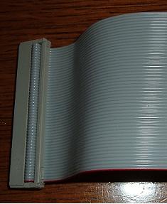
Swell pedals are treated in the same manner as key and stop contacts. A well known make of swell pedal for an electric action console consists of a number of springy contact wires (typically 16) together with a phosphor-bronze wiper which moves across the array of contacts as the pedal is operated. In a traditional electric action each wire would be connected directly to the various magnets in the swell shutter mechanism (a whiffle-tree, etc). As far as the multiplexer is concerned, the contact array looks just like a miniature keyboard with 16 notes, and it can therefore be scanned as part of the entire console scanning sequence. Those contacts which are in electrical contact with the wiper will result in an “on” pulse being transmitted, whereas the others will not. In the organ chamber the de-multiplexer effectively re-creates the original 16 wires which ordinarily would have been connected directly to the contacts in the swell pedal, and these are then connected to the 16 magnets in the swell shutter action. Combination pistons are not usually part of a multiplex transmission scheme unless part of the mechanism is in the organ chamber. This would be unusual today although it was not always thus, so normally we find the whole of the combination mechanism confined to the console alone. Nevertheless the subject of electronic stop control (capture systems and the like) will be discussed later in this article as it also, like electronic transmission, is an application area for modern electronics in organ building. Pulse code modulation and MIDI It is useful to define a few more terms at this point, not only for the sake of completeness, but because they are frequently encountered in the literature dealing with electronic transmission. The term pulse code modulation (PCM) is used to describe a system which communicates information from one point to another by using a series of electrical pulses. Self-evidently, an electronic transmission is a PCM system. The use of the word code is important here as it implies that different types of pulse trains, or codes, can be used to indicate which notes et cetera are on or off. The description in earlier paragraphs was of the simplest type of electronic transmission in which single pulses defined the state of each note or stop in succession. However there are many types of code, most of which use several pulses to indicate the state of a single note. There are sound engineering reasons for this apparent complication which will not be entered into here, but it is worth mentioning the name of one such coding system. This is the RS232 code, a very widely used scheme. For example, it is used for the link between a personal computer and a printer if the serial interface option is employed. For the purposes of this article, a more relevant application is that of MIDI. MIDI stands for Musical Instrument Digital Interface. It arose some years ago when many manufacturers first got engaged in designing digital electronic musical instruments such as synthesisers. Because these instruments used computer technology it was convenient to also use a keyboard scanning system to indicate to the computer which notes were being keyed. In a commendable display of co-operation the major manufacturers got together to decide on a common pulse coding standard for their keyboard scanning systems so that all of their products could be linked together. The result is that, for example, the synthesisers of one manufacturer can be played from the keyboards of another. This electronic transmission standard is called MIDI, and it is in effect a high speed RS232 data link. In the organ world most electronic organs use it and so do most of the manufacturers of electronic transmission systems for pipe organs. In other words, the pulse trains racing around in an electronic transmission will often look just like those in a cable linking two synthesisers used by a pop music band. This enables a pipe organ using a MIDI-compatible transmission to play, or be played by, any other compatible instrument. Whether you regard this as a hindrance, a help or merely a gimmick is a subjective judgement. For the purposes of this article it is necessary to point out that the facility often exists. If you want to use it, you only have to acquire a suitable MIDI lead with DIN connectors on each end, and plug it into the instruments which you want to link together. [The largely unfortunate and inartistic musical implications of MIDI when used in organs is discussed in the article MIDI for Organists]. Coupling We can now return to complete the discussion about the advantages of electronic transmission, and one advantage is so significant that it needs to be mentioned separately. This concerns couplers. We have noted already that in traditional electric actions coupling is usually achieved by multi-contact relays which connect the key contacts of the coupled manuals together. Such relays have 61 contacts for five octave keyboards, and they are large and expensive. Moreover, the labour involved in wiring up the hundreds of relay contacts in an organ with many couplers leads to significant cost implications. There are also reliability implications in this approach in view of the large number of contacts. Frequent cleaning is usually called for, just as it was in old fashioned telephone exchanges using similar relays and from which those used in organs were derived. In an electronic transmission all of this can be dispensed with, and in theory a cost saving should accrue. If the swell to great coupler, say, is drawn, then circuitry is activated in the console multiplexer which simply inserts a duplicate set of “on” pulses in the pulse train corresponding to the swell keyboard. These duplicate pulses define those notes of the great keyboard which are being keyed during a particular scan. By this means all notes which are keyed on the great will also sound on the swell, as required. Although it is not perhaps conceptually simple to get one’s mind around this technique at first, it is nevertheless extremely simple to implement electronically. Only a few tiny integrated circuits are necessary in the multiplexer for the entire coupler complement. Interconnections Some remarks have been made already about the reduction in the number of interconnections which electronic transmission confers on an electric action, and it is useful to pause and summarise them at this point. The most obvious example, as we have observed, is the long cable connecting the console to the organ. However within the console there are other opportunities to reduce the interconnection burden and the absence of coupler relays, as mentioned above, is one of them. Yet another example, not yet mentioned, occurs in the interconnections between the key contacts and the multiplexer. Perhaps surprisingly, it is not necessary to connect each note on a keyboard directly to the multiplexer. If it was, then 61 wires would be required for the usual five octaves. However the fact that the multiplexer scans the keys in sequence means that the number of wires required can be reduced very considerably. The reasoning behind this will not be entered into but it can be remarked that if binary coding is used, then only 7 wires or so would be needed per keyboard instead of 61. Each of the 7 wires is connected to several keys in parallel via electronic logic gates. The interconnection situation has been emphasised again here for three reasons. Firstly, it will help to explain why there are apparently so few wires inside a properly designed console using electronic transmission if you look inside it. Secondly, those wires are generally in the form of computer-type ribbon cables, and these can be joined onto other equipment rapidly and cheaply by using modern insulation-displacement connectors (IDC’s) as illustrated below. The third reason follows from the previous two, and it is that these economies result in a console which should be much cheaper, quicker and easier to wire than the old fashioned approach to electric action with its cable looms and innumerable soldered joints.
A 36-way multicore ribbon cable terminated in an IDC (insulation displacement connector). These are used widely in modern digital equipment, including electronic (solid state) organ transmission systems. It takes only a few seconds to attach the cable to the connector using a special tool or even just a small vice, whereupon all the separate wires are automatically connected to their proper pins in the socket which can then be mated with the corresponding plug. Much quicker than laboriously soldering each wire by hand! However, it is important to note that modern wiring techniques such as these are just as applicable to old fashioned electromechanical organ actions as they are to electronic transmissions. They can be used to update and give a new lease of life to such actions by replacing the old cable looms with ribbon cables and IDC connectors. Disadvantages of electronic transmission Having outlined the main advantages of electronic transmission, a balanced article also needs to look at the disadvantages. Cost and Reliability It will be apparent that relative cheapness ought to be one of the main advantages of electronic transmission, and this is achieved through a dramatic reduction in wires, connections, soldered joints, etc. On the face of it, therefore, one would expect that there would also be a corresponding increase in reliability. Reports differ on this matter, some of them claiming vastly increased reliability compared to earlier relay-based systems whereas others indicate a continuing struggle with an obviously unreliable electronic transmission. When interpreting such reports, it is necessary to tease out exactly what people expect from an action and thus what they regard as reliable or not. One such related to an organ whose relays were replaced by an electronic transmission after about 10 years, prior to which they required periodic cleaning of the contacts. Some would describe such a situation as tolerable and, given the need for routine maintenance, generally reliable whereas others would not. On balance the general tenor of user experiences suggests that it would be overstating the case to say that electronic transmissions are unreliable. However it is certainly true that they bring with them their own set of peculiarities which partially outweigh the advantages one might have expected, and these deserve further discussion. Complete failure is by no means unknown. This was embarrassingly demonstrated in the case of the new Bridgewater Hall organ during the recent BBC TV programme “Made in Manchester”. (Although it was not made clear, this organ was most definitely not made in Manchester! An article on it appeared in reference 2). The unfortunate organist, sitting at the moveable console, could do nothing until the organ builder in the organ chamber managed to sort things out. It appeared that there was a connector problem on the fibre optic cable, but fortunately this only occurred during rehearsal. Since this unfortunate event was broadcast publicly, I do not need to apologise for mentioning it here as a cautionary tale. A more serious case of complete failure is that of Notre Dame cathedral in Paris. It is more serious because of the implications following from the design of the system. But since this case raises other issues, a discussion of the matter will be left until later. A relatively common problem is that certain notes sometimes do not sound, then they may re-appear at a later time. Or notes that are not wanted do sound, causing intermittent cyphers. Such random faults may not always be caused by the transmission, but in some cases they undoubtedly are. One occasion in which a particularly bad crop of such faults occurred was traced to the coaxial cable being placed close to a fluorescent light fitting. The high frequency radiation from this interfered with the signals in the cable and resulted in the problem. Another example affected the organ in a church near a high power radio transmitter, which caused long delays to be sometimes added to the time taken for the organ to respond to the player. These are electromagnetic compatibility problems, and similar manifestations could conceivably arise through the use of radio microphones or mobile phones in the auditorium. Repairability I am not sure that the word repairability is in the dictionary, but hopefully it will be accepted here. I refer to the ease or otherwise with which something can be repaired. With conventional electric actions not containing electronics it is usually straightforward to discover the cause of a fault, although it can take some time prodding around with a voltmeter or ohmmeter. Most people with an elementary understanding of electric actions would be able to do this, and any organ builder certainly would even if he had not built the organ in question. These attributes can be important when things go wrong at the most inopportune times, as is the way of things. Matters are very different with electronic transmissions. These contain electronic assemblies whose functions are sophisticated and frequently obscure even to an expert and even if one has the service manual available, which would be a rare occurrence. Repair is usually on the basis of module replacement, in which a complete printed circuit card would be replaced if it was found to contain a defect, but even locating the module can require the use of special test equipment. It is unlikely that emergency repairs of this nature could be undertaken rapidly, as they would more often than not need the attention of a specialist. One frequently hears the argument that modern electronics is so reliable that such matters should not cause concern. In reply to this, I can only say that my experience of some 30 years in wrestling with electronics in its various guises paints a very different picture. Integrated circuits and transistors can malfunction or fail in myriad ways, sometimes over a long period. One particularly infuriating mode of failure, by no means uncommon, relates to the ambient temperature or even the humidity. In a building where these parameters are poorly regulated, such as a church, problems can occur that would never arise in the benign environment of an electronics development laboratory. This means that systems will sometimes work when switched on but sometimes they will not, or that they will begin to fail intermittently after a period of operation. More often than not this will be in the middle of a service. To a person who expresses such touching faith in electronics, I would point to the number of companies which thrive on repairing modern consumer electronics ranging from CD players to computers. These systems employ just the same sort of technology used in electronic transmissions. And how often is it that an item cannot be repaired at all, or the repair takes weeks? An eventuality which cannot be ignored in large buildings such as churches is a lightning strike. It is quite possible for all the electronics in an organ to be completely destroyed by the most minor lightning discharge or one which occurs nearby, even if no other damage is apparent in the building. This is because solid state semiconductor circuitry cannot tolerate much in the way of over-voltage conditions, and destruction will occur at levels far below those necessary to cause physical manifestations such as burning or fire. Independent confirmation of the sort of damage that can be encountered can be found in reference 3 relating to St. Eustache in Paris, and reference 4 relating to St. Mary’s Cathedral, Edinburgh. Old fashioned electric actions containing only relays are more robust and they will only fail if the discharge is severe enough to burn the wiring or other components. In these circumstances the amount of energy required is not far below that which would destroy the entire organ or the building in any case. Obsolescence Obsolescence is related to repairability in that sometimes a system cannot be repaired because the necessary components can no longer be obtained. Certain electronic transmissions can become obsolete rapidly, with the parts they use going out of production in less than a year. This is because components such as microprocessors may be used together with memory chips and the like. We are all familiar with personal computers which are hopelessly out of date almost before one has gained some familiarity with them, and this is partly because of the rapid rate of progress in integrated circuit (IC) technology. If low performance industry standard IC’s are used in the transmission, such as the Z80 family of peripheral controllers, then the obsolescence problem is unlikely to be serious. Such parts have been around for nearly 20 years and will probably remain available for some time into the future. But a more sophisticated system may become difficult or impossible to repair in quite a short time. Another problem, which might result in some transmissions becoming unserviceable on 1 January 2000, is due to the Millenium Bug, that problem which will affect many computer systems when the date rolls over to the year 2000. If your system incorporates microprocessors it will be advisable to check with the supplier whether it is “Year 2000 Compliant”. And if you will be purchasing a system between now and then you should do the same. The obsolescence problem brings us back to the situation at Notre Dame in Paris. The installation of an electronic transmission in this famous organ was described in references 5 and 6. Among other things it contained multiple computers and, bizarrely, a vocal synthesiser. A report of what appears to be chronic unreliability at a catastrophic level is in reference 7; it resulted in the system having to be replaced but not before the manufacturers had apparently removed the software as part of their dispute with the Cathedral. This, of course, would render any computer based system completely inoperable. To conclude this section on obsolescence, it is worth remarking that the traditional approach to electric actions using relays instead of electronics resulted in many organs which are still going strong after 60 years’ service or more. This longevity has in general been achieved not necessarily because of superior reliability but because of better repairability and survivability, and hardly any problems due to components becoming obsolete. In other words, if these older systems do go wrong, it is usually straightforward to put them right. Scanning delay The subject of scanning delay brings us to one of the most controversial issues surrounding electronic transmission as far as the player is concerned, and it is the main reason why this article was commissioned. It is an indisputable fact there will always be some delay inserted by the transmission in addition to that caused by other factors. Moreover, the transmission-related delays will sometimes vary in an unpredictable manner. There can be no argument but that some world class players feel uneasy when playing an organ with electronic transmission. I have their word for it in some cases myself. In extreme cases there is a delay so perceptible that its existence cannot be denied, but a more common feeling is one of a disconcerting detachment from the instrument in a way that is sometimes difficult to define. However the results can be more tangible; one case described to me by a professional organist resulted in his almost complete inability to play a particularly pianistic piece on the positive of a certain organ with electronic transmission whereas he had no problem on the other departments which used a different system. Obviously, the scanning rate has to be as high as possible. The human organism is sensitive to the most minute relative delays between sensory inputs. Our two ears, for example, locate the position of sound sources by timing their arrivals to less than one millisecond (thousandth of a second). Delay between pressing a note on an organ and hearing a sound is also detectable for very small time intervals, and this is why we often find tubular pneumatic actions so unpleasant. But however objectionable the time delay might be on a pneumatic action, the fact is that the delay remains constant and in time most organists can get used to it. This is not so for many electronic transmissions. To see why this is so, consider the situation in which you are by coincidence about to key a note just as the multiplexer is about to sample it. In this situation there will be no additional delay introduced by the transmission. But if you were to key the note fractionally after the multiplexer had sampled it, so that the scan had moved on to the adjacent note for example, then the delay introduced by the transmission will equal one whole scan cycle. Some systems apparently scan at the slow rate of 25 scans per second, which means that the delay can vary randomly between zero and 40 milliseconds. A delay of 40 milliseconds is highly noticeable, and would equal that of a pneumatic action with at least 25 feet of tubing between console and pipes. With an electronic transmission the additional fact that it may not be constant will be most disconcerting to a player. It would certainly explain the sort of floating and detached feeling sometimes reported. Playing demisemiquavers at crotchet = 60 means that notes are being played at the not unusual rate of 8 per second, that is, with 125 milliseconds between notes. An additional but random delay of 40 milliseconds in this situation would be plainly intolerable and the listeners, let alone the player, would feel that something was badly wrong. Fortunately things will not generally be as bad as this for two reasons. Firstly the scan rate is usually higher than 25 per second, and secondly it is possible to include a feature (called sample and hold) which evens out the delays so that they become constant. Even so, scan rates are frequently not fast enough, and sample-hold appears not to be universally used. Given that we are so sensitive to time delays, it is reasonable to demand that the additional delays introduced by the transmission are perceptually tolerable, say less than a millisecond. For this to be so scan rates in excess of 1000 per second could legitimately be demanded. Such rates are rare but not difficult in principle, as they imply an information rate within the system of less than one million bits per second even for a very large organ. This would be straightforward to achieve, although for technical reasons it might cause difficulties if MIDI compatibility is required. In addition to a sufficiently fast scan rate it is also reasonable to always insist on the incorporation of a sample and hold feature. Finally, it is worth noting that problems due to scanning delays may be worse when extension is used. There is no easy way of knowing how the system activates pipes on unit chests relative to the scanning cycle. To understand this statement, consider first an organ without extension in which all pipes are on slider chests. When the pallet corresponding to a particular note is opened, all the pipes whose stops are drawn will speak more or less simultaneously. If there are relative delays in the onset of speech between the various stops in this situation they will not be caused by scanning delays. But if these pipes are on unit chests, as they will be in an extension organ, they will all have separate magnets. In such a case the design of the transmission may be such that they are not activated simultaneously, giving rise to delays between stops which ought to speak simultaneously. Aesthetic considerations The variable esteem in which the organ is held not only by other musicians but by organists themselves results in many opinions about its intrinsic musicality. Even some of those who have made the organ their career find much of its repertoire unmusical and find the instrument not worth playing were it not for the works of J S Bach (see, for example, reference 8). It is partly for reasons such as these that many see a mechanical action as the only one which maintains what musical credibility the organ has. If a mechanical action cannot be used there are presumably strong enough reasons which justify a good electro-pneumatic action, but any articulation which would otherwise have been possible is thereby swept away (reference 9). In these circumstances, to deliberately introduce the additional shortcomings of an electronic transmission as noted in this article must surely put instruments which use it at one more remove from many musicians. Among other things, it puts pipe organs into the same category as electronic organs as far as control by the executant is concerned. Although the potential exists for relative cheapness and enhanced reliability together with an undoubted engineering elegance, the reputation of the modern organ as little more than a box of tricks gets more difficult to refute if an electronic transmission is used. The orchestra player’s jibe “whoever heard of a violin played by electric action” gets even more embarrassing if that action is multiplexed. The application of electronics to organs sometimes looks like technology gone mad. At its most extreme, the sort of débacles experienced in recent years in some of the world’s most important organs is nothing short of an embarrassment to the community of organ builders, organ advisers and organists alike. The situation is not helped by the coyness of those manufacturers who decline to reveal basic details of their system such as the scan rate and whether sample-hold is used. Conclusions This article has surveyed the main advantages and disadvantages of electronic transmissions, but only individual purchasers can decide what weight to apply to each of these factors. The adage that what is one man’s meat is another’s poison applies just as strongly to this area as to many others in life. However the following approach may be helpful if you get involved in deciding whether to go for an electronic transmission, and it is assumed you will be seeking competitive tenders for a new organ or a rebuild of one in which electric action is the only option: 1. Unless the console absolutely has to be moveable and disconnectable on a frequent basis, consider whether a traditional electric action without electronics could be used. Such an action suffers none of the disadvantages associated with electronics mentioned in this article. However it may be more expensive than an electronic transmission, and there may be reliability implications. 2. To establish more precisely the price differential, ask the bidders to cost both options. It will concentrate their minds if you make it clear that, all other things being equal, you incline towards a non-electronic solution. 3. If a rebuild of an organ with a traditional electric action is being considered, do not allow the existing wiring looms to be ripped out without the most careful consideration. In normal circumstances these have a very long life; copper does not wear out! However the insulation does, and rubber or cotton covered wiring dating from the 1930’s or so may have to be replaced. Nevertheless, the point is that much of the labour costs involved in the electrical side of organ actions are related to the wiring and interconnections, and therefore if the looms are reusable then much needless expense could be saved if the action is to be rebuilt along traditional lines. 4. Existing coupler relays, reverser units, etc. may require replacement, so consider whether replacing them with electromagnetic as opposed to solid state relays might be the better approach. These would have better survivability in the event of a lightning strike, and be less at the mercy of obsolescence. The expense of using units specifically designed for organ applications might be reduced by using standard modern relays as used in the electronics industry, and at the same time reliability might be increased. For example, a coupler relay with the usual 61 contacts could be made up from 16 relays each having 4 contacts. If more contacts per relay were to be used then of course fewer relays would be required. Such units are sealed, small, cheap, exceedingly reliable and typically they have a life in excess of 10 million operations. They are available in plug-in versions which would assist rapid repairs in the event of replacements being needed. They could readily be assembled in a form such that they could be connected directly to the existing wiring looms. Similarly, reverser units could be made up from a pair of such relays [see Appendix 1 to the article The Evolution of Electric Actions]. It is unlikely that the contacts on such relays would require the amount of cleaning, or indeed any, which the exposed banks of contacts on bespoke organ relays seem to demand. An action refurbished conservatively along these lines could be given a new lease of life of many years, with none of the disadvantages associated with electronics. Unless extensive tonal alterations or major additions to the coupler complement are required as part of the rebuild, what would be the point of replacing the entire mechanism with an electronic transmission when much of it might be reusable? Postscript - Electronic combination systems Combination pistons have little to do with whether an electronic transmission is used or not, other than the fact that in some systems the same box of electronics will cater for both functions. Modern combination capture systems have multiple memories so that several organists can retrieve their own settings, or a single organist can use different memories for different pieces. In addition there are more exotic functions available such as sequencing. The reason for introducing this subject here is to emphasise that, unlike the electric action itself, it is almost impossible to visualise a comprehensive stop control system which does not use electronics. It has been suggested above that a traditional approach using relays could still be used for the action if desired, but for the combination system (assuming you want a capture system) it would be inconceivable to do it in any other way than by using electronics. This is because of the need for multiple non-volatile memories in which to store the piston settings. The old systems developed in the 1930’s by builders such as Willis, HNB and Compton did use relays, but these were specially made items which are now unobtainable. In any case, they only stored one setting at a time. It is therefore almost inconceivable that such a system could be reproduced today. Therefore if a fully flexible system is required for stop control there is no practical alternative to electronics, and some of the disadvantages relating to repairability and survivability listed above will apply. These could only be avoided by accepting a lower specification system, such as a simple setter board. For ease of access all of the following references are restricted to those which have previously appeared in Organists' Review: 1. “Electronic Organs”, Colin Pykett, August 1998, p. 220. Also available on this website (read). 2. “The new Marcussen organ in the Bridgewater Hall, Manchester”, Roger Fisher, May 1997, p. 93 3. Letter to the editor, Robert Kay, February 1995, p.8 4. Letter to the editor, Timothy Byram-Wigfield, February 1996, p.5 5. “The evolution of the grand organ in Notre-Dame in Paris (Part I)” , Lasala and Lane, August 1994, p.224 6. “The evolution of the grand organ in Notre-Dame in Paris (Part II)”, Lasala and Lane, November 1994, p.312 7. Letter to the editor, Mark Smee, November 1995, p.257 8. Alan Spedding talks to Douglas Carrington, February 1998, p.8 9. “Touch sensitivity and transient effects in mechanical action organs”, Colin Pykett, November 1996, p. 285. Also
available on this website (read).
|