


|
|
|
Console scanning, MIDI and PIC Microcontrollers for Virtual Pipe Organs by Colin Pykett
Posted: 2 April 2012 Last revised: 14 May 2012 Copyright © C E Pykett 2012
Abstract. This article outlines the main issues involved in scanning the contacts in an organ console or keydesk so that it can be used to play a virtual pipe organ (VPO) optimised for the highest performance. Although MIDI is used universally as the messaging protocol by VPOs, its relatively high contribution to the overall latency (the delay between keying a note and hearing the result) makes it undesirable when the system is to be used by discerning players. Therefore an alternative technique is described in which the computer hosting the VPO also scans the console, and this results in significantly lower latency. The issues are illustrated by referring to the Prog Organ VPO which can operate in both MIDI and direct scanning modes, thereby enabling them to be directly compared..
Contents (click on the headings to access the desired section)
A virtual pipe organ (VPO) uses the processing power of a modern personal computer to simulate a pipe organ by storing the waveforms of many individual pipes in its memory and then replaying them on demand. There are two ways to play a virtual pipe organ. One is to connect some form of keydesk or console to the computer so that one can pretend one is playing a pipe organ in the usual manner in real time. Usually the console sends its commands to the PC using MIDI. The other way to ‘play’ the VPO is to sit back and let the computer issue the MIDI commands from a file already on its hard disc, rather like the pianola of a century ago playing a paper music roll. The file might have been prepared previously by yourself or somebody else in non-real time, or it might have been downloaded from the huge choice available on the Internet. The first method places more demands on the VPO because it immediately exposes noticeable latency in the system in an unflattering manner - latency is the time delay between pressing the keys and hearing the sounds. By contrast, latency is not much of an issue when the instrument plays itself. This might be one reason why some people are obviously using the second method when uploading their efforts to YouTube, because the latency of some VPOs of my acquaintance makes them unplayable in real time using method one. When I was developing my Prog Organ VPO I came up against this problem early on. Prog Organ is a computer program which in effect sits between the player at the console and an array of synthesisers which generate the sounds, and I decided that it must not add appreciably to the overall latency of the system as a whole. In quantitative terms this meant that the total latency of the instrument as experienced by the player should not exceed 50 milliseconds in worst-case circumstances, such as when playing a heavy chord on full organ. This is because 50 milliseconds is typical of the latency of a good pipe organ action [1]. Without going into a lot of detail, this meant the latency overhead added by the Prog Organ software itself to that of the other components of the system such as the synthesisers should not be more than a few milliseconds, and certainly less than five. This design requirement made the use of MIDI undesirable, as it is an inherently slow system. Not only does MIDI require all the contacts on the console to be scanned, and this in itself takes time, but it then consumes at least one millisecond to send a single message to the computer each time it detects that a single contact has changed state. Therefore playing a full chord on manuals and pedals can consume many milliseconds of precious latency, and in these (and other) circumstances it can definitely become noticeable to the player. Thus MIDI degrades the latency performance of any VPO. Invented in 1981 when computers such as the then-new IBM PC (which also appeared in 1981) were primitive and slow, MIDI was never intended to be anything other than a rather cheap and cheerful convenience for pop musicians, and I have described its undesirable consequences for their classical brethren elsewhere on this website [2]. So those who are interested in using VPOs for serious musical purposes might decide to consider the matter carefully. It is worth pointing out that certain manufacturers of high quality pipe organ transmission systems make it clear that they no longer use MIDI. This article outlines how Prog Organ achieves its very low latency figure using a non-MIDI approach to controlling the console of a VPO. However this makes it unconventional compared to all other VPOs, so the article then goes on to show how the console control system for Prog Organ can be ‘MIDIfied’ at the expense of increased latency. This enables the same console to be used to control other VPOs as well. The article is not an advertisement for Prog Organ, which is not currently on offer as a product. It uses Prog Organ to illustrate some aspects of console control which are of more general relevance to the virtual pipe organ scene. Because a VPO uses a computer to generate the sounds, one can also use it to actively control the console rather than just passively waiting for MIDI messages to trickle in. Therefore the Prog Organ program instructs the computer to scan continuously all the contacts in the console very rapidly via one of its standard ports. When I was first designing the system some years ago, all PCs had a so-called parallel port which was commonly used to control printers and the like. This has since become a legacy feature not found on modern PCs, but the same principles apply to console scanning using any other port. The USB port of today is a fast serial port which can be used equally well. However a parallel port can be made available on the majority of recent desktop computers if one installs a suitable PCI riser adapter, as these are still widely available at the time of writing (2012). It might be useful to describe first how a console scanner works. Let us take the example of a five-octave organ keyboard with 61 notes and consider the widely used technique of matrix addressing.
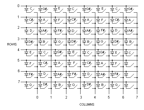
Figure 1. Typical keyboard scanner wiring matrix
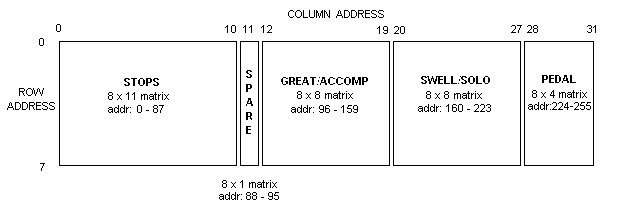
Figure 1 shows how the contacts of a keyboard can be wired into a switch matrix with 8 rows and 8 columns. (With 61 notes this leaves 3 spare, which can be used for any other purpose such as couplers, pistons, tremulants, etc). Each contact must have a series diode for the reason explained presently. In the diagram the key contact at top left corresponds to bottom C. Successive notes then run sequentially down column 0, then down column 1, and so on. In practice it does not matter how they are wired but the arrangement shown is one logical example. Assume the console scanner first puts a logic high level (binary ‘1’ - say 5 volts) onto row 0 of the matrix. Then if bottom C happens to be keyed, a ‘1’ will appear on column 0 only. Likewise, if middle C happens to be keyed as well, a ‘1’ will also arise on column 3. All other columns will remain at ‘0’. Therefore by scanning across all 8 columns while keeping row 0 at ‘1’, the matrix coordinates (row and column addresses) of all depressed keys on row 0 will be obtained in sequence by noting when a ‘1’ appears on a particular column. From these coordinates the computer can then work out which notes are currently keyed. The scanner then returns row 0 to logic ‘0’ (zero volts say) and puts a ‘1’ on row 1 instead, again scanning all the columns to find which keys are pressed. This continues until all the rows and columns have been scanned. This method of scanning a keyboard is used purely for economy of wiring. Instead of requiring 61 wires from each keyboard going into the scanner, only 16 are needed (8 rows plus 8 columns). This is a considerable simplification. But note that it does not reduce the time required to scan the keyboard because the 61 contacts still have to be scanned individually. In fact, because 64 contacts are actually scanned in this example, using matrixed rather than direct addressing will slightly increase the scan time for this keyboard. The diodes are necessary to prevent ‘phantom’ switch closures. Consider what would happen if bottom C (row 0/column 0) and bottom G (row 7/column 0) were pressed simultaneously without diodes being used. When the scanner activates row 0 with a ‘1’, row 7 will also be activated via current flowing in the reverse direction through the bottom G key contact. Thus notes keyed on row 7 would also be detected while the scanner was deluded into thinking it was only scanning row 0. This would cause mayhem in a system without diodes to prevent it, with the result that many unwanted notes would sound as the system scanned the contact array. The matrix idea can be extended to encompass an entire console. Figure 2 shows one of many possible scanner address maps for a console with two manuals and pedals. Up to 88 stops plus some spare (unused) contacts are also mapped into the matrix. As before, there are 8 rows in the matrix but this time 32 columns. Each manual keyboard occupies a block of 8 x 8 contacts as per Figure 1, the pedals a block of 8 x 4 and the stops a block of 8 x 11. There are 256 contacts in total in this console including the spares.
Figure
2. Typical console scan address map
These 256 contacts can be scanned using the 8 bit data bus of a computer’s parallel port, because when all bits of the bus are low this represents contact number 0, and when all are high it represents contact number 255. To address the contacts in matrix fashion, three bits of the bus are used to scan the 8 rows, with the remaining five bits scanning the 32 columns. The complete circuit diagram of the scanner is shown in Figure 3 for those who might find it of interest.
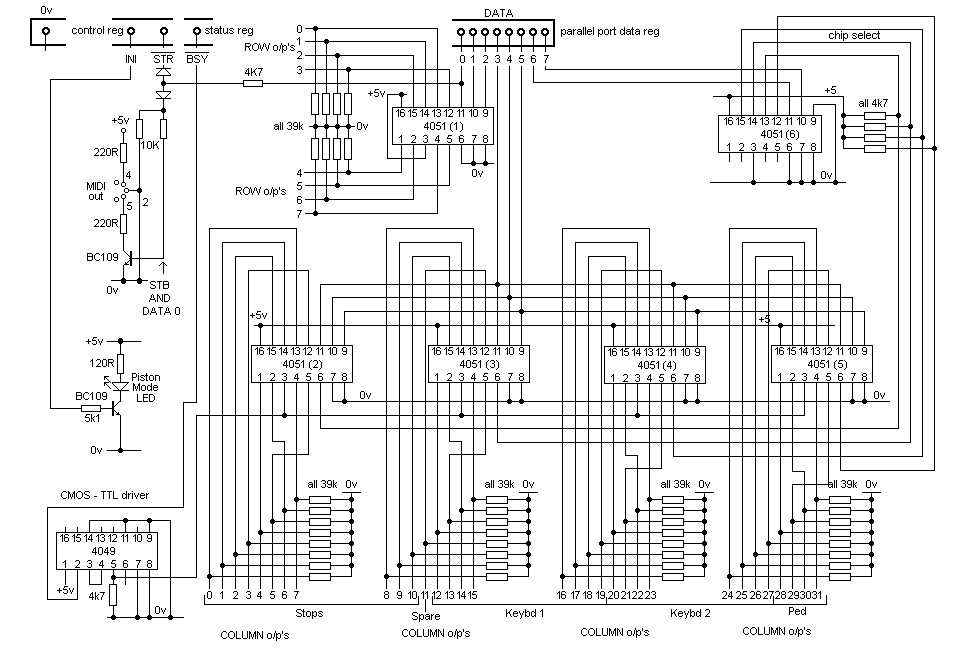
Figure
3. Schematic diagram of the
parallel port console scanner
Ignoring for the moment the two transistor circuits on the left of the diagram, the 8 bit data register of the parallel port is shown at top centre. This can be loaded with any number between 0 and 255 by the computer to address any contact. The least significant three bits of the register (0 - 2) are decoded into row addresses 0 - 7 by chip 4051(1), and the most significant five bits (3 - 7) are decoded into column addresses 0 - 31 by the remaining 4051 chips. These column addresses are at the bottom of the diagram and they correspond to the console address map shown in Figure 2. The 39k snubbing resistors ensure that all row and column lines promptly return to zero volts when they are not forced into a logic high state (i.e. when not actually being addressed). These materially speed up the maximum possible scan speed by absorbing the capacitive energy stored in the system. Significant parasitic capacitance arises from the lengths of wiring between the scanner circuitry and the contacts inside the console, and it is an important matter to take into account when designing a system which must run at high speed. An even more effective solution would require the use of line driver circuits and transmission line wiring techniques, but one has to stop at a point where a reasonable compromise between complexity and performance has been arrived at. Whenever a switch contact at the current row/column address is found to be on, a signal in the form of a short pulse passes from the 4049 interface chip back to the BSY line in the parallel port status register to inform the computer that a note has been keyed, a stop switched on, etc. The 4049 is necessary to interface the CMOS logic of the scanner board into the LSTTL logic of the parallel port within the computer. A picture of this scanner circuit in the form of a compact PCB made by Martin Hickman is at Figure 4.
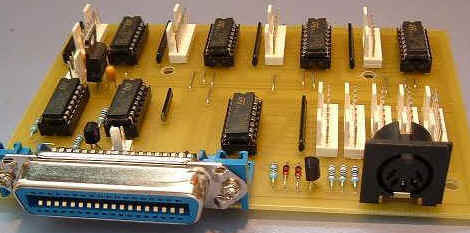
Figure
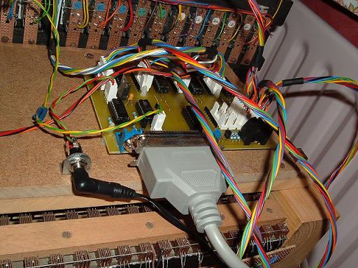
4. The parallel port scanner (PCB by Martin Hickman) The large blue ‘Centronics’ socket was incorporated because it enabled a standard IBM PC printer cable to be used between the computer and the scanner board. All the wired connections between the PCB and the console row and column contacts use the white Molex connectors which can also be seen. The PCB in situ inside an actual console is shown in Figure 5.
Figure
5. The parallel port scanner in
situ inside a console
256 contacts are comfortably enough for almost any two manual organ, but more can be provided for larger consoles by adding an additional scanner board. A second board will provide a second ‘page’ of 256 contacts, allowing up to 512 contacts in total which will cater for almost any conceivable instrument. The boards are selected by addressing them using one of the ancillary control lines of the parallel port. As already mentioned, scanning speed is limited in practice by the capacitance of the console wiring, not the computer. On the contrary, it is necessary to restrict the speed of the scanning algorithm within the Prog Organ computer program so that it does not overclock the scanner. About 500 scans per second (256 contacts per scan) is a reasonable practical speed using this system if it is to run completely reliably, meaning that each complete scan of the entire console takes about 2 msec. The scanner runs continuously at this speed, with detected contact closures and openings being stacked in a processing queue within the computer program. Even when tested with an old and slow 360MHz PC the processing queue never built up to more than a few entries, and at computer clock speeds over 1 GHz the entries are processed instantly as soon as they arrive. This demonstrates the speed of the Prog Organ program itself, and it shows that the design goal of a system which adds a latency overhead of only a few milliseconds was achieved. Nevertheless, like all VPOs, Prog Organ is at the mercy of the sound synthesisers used with it because these can dominate the total latency of the system as a musical instrument from the player’s point of view. All Windows-compatible synths can be used with Prog Organ, and hardware synths are preferable in terms of latency to software ones. The hardware synths in high quality sound cards enable the total latency of the system to be kept well under the design aim of 50 milliseconds (recall that this is the latency of a good pipe organ), with 20 milliseconds being a maximum figure realised in practice. However the use of software synths can degrade performance considerably, and this can only be overcome by using a faster computer.
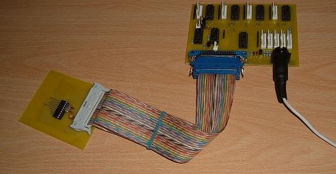
It is worth mentioning an advantage of this type of scanning, which is that all controls on the console are initialised when the system is switched on. Therefore all stops which have been left 'on', the position of the swell pedals, etc will be acknowledged by Prog Organ from the outset of the playing session. This is a convenience to the player, especially as some like to leave certain stops such as 'great to pedal pistons coupled' permanently drawn. It brings the system closer to what the player would expect to happen on most pipe organs. By contrast, most MIDI systems do not do this. In this case all the stops have to be cancelled, the swell pedals exercised, etc before any MIDI signals are sent to the VPO to initialise the state of the console. The use of the parallel port (or any other) for console scanning delivers high performance in terms of a low latency overhead, but it makes Prog Organ and this console scanner non-standard as far as digital musical instruments are concerned. Therefore the software was designed from the outset to also include a conventional MIDI input option. When this is used the console scanner just outlined obviously cannot be employed exactly in the form described. Therefore the scanner hardware itself was also designed to incorporate a MIDI option. Instead of driving the scanner board from the PC, a PIC microcontroller sub-system was developed which emulates a parallel port. This is simply plugged into the Centronics socket on the main scanner board, which therefore continues to think it is being driven from a parallel port. But the PIC also instructs the system to emit MIDI messages from the DIN socket which observant readers might have noticed already in Figure 4. (This socket performs no function when parallel port scanning driven by a PC is used).
Figure
6. PIC-driven MIDI console scanner
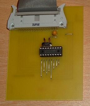
The necessary add-on consists of a small PCB containing an inexpensive 18 pin PIC chip (16F627) with a few ancillary components. This plugs into the Centronics socket on the main board as shown in Figure 6, which also shows the MIDI lead emerging from the DIN socket. This is connected at its far end to a MIDI port on the computer which is running either Prog Organ or any other VPO or MIDI-compatible instrument. This is possible because, now the console scanner has been ‘MIDIfied’, it can be used with a much wider range of instruments, not just Prog Organ. A close-up photograph of the parallel port emulator board is at Figure 7.
Figure
7. Parallel port emulator using a
PIC microcontroller
Console scanning is now done by the PIC rather than the PC running Prog Organ, and the PIC is crystal-controlled because MIDI systems demand precise pulse timing. The two boards together can scan up to 256 contacts, thus a second pair of boards would be used when more contacts were required for a large console. Each pair would run independently and asynchronously, with their respective MIDI output signals being merged within the computer. (A more detailed discussion about merging multiple MIDI streams appears below). When the PIC detects that any contact in the console has changed state, it sends the appropriate MIDI message as a serial bit stream down the interconnecting ribbon cable. This is received on the main PCB at bit 0 of the Centronics socket data register (see Figure 3) and passed to a standard MIDI current-loop interface circuit using the BC109 transistor. The MIDI signal then appears at the MIDI OUT socket in the collector circuit of the transistor. The big drawback of this arrangement is again the drawback of MIDI - its slowness. Each MIDI message takes at least one millisecond to send, and in practice it is usually longer because MIDI receivers at the far end of the link (i.e. in the PC) often fall over if messages arrive too thick and fast. Either notes will not respond at all, or (more infuriatingly) they remain sounding when keys are released. Apart from these Note On and Note Off messages, some of the worst perpetrators of excessive latency in any MIDI system are Continuous Controller (CC) controls such as the swell pedals in a VPO. Often these consist of a variable resistor (potentiometer) attached to the swell pedal, and as they move they send a continuous avalanche of messages which crowd out everything else, that is if they do not cause the system to choke. Therefore for all these reasons I reluctantly feel it prudent to assist the receiver by including a gap between MIDI messages by writing the PIC software appropriately, but this only increases latency still further of course. In any case, the one millisecond figure applies only to MIDI ‘channel’ messages of the type just discussed. If 'system exclusive' (SYSEX) messages are used for some switches such as stops or pistons (as they sometimes are in MIDI organ control systems) then the delay can be anything at all. This is because the structure and format of SYSEX messages are left to the whim of the system designer. For this reason they are to be deprecated in high performance systems and I never use them myself. There is also an additional problem. The parallel port scanner described earlier is able to scan continuously at high speed because its messages are queued inside a very fast PC, and the queue is emptied at least as fast as it is filled (in practice it is emptied faster). By contrast, when MIDI is used the scan has to be interrupted while each MIDI message is sent if you do not want the system to fall over. Otherwise it might choke to death if it continues to scan while messages are being dealt with, because the messages from a vigorous performer cannot be queued indefinitely inside the PIC when the queue can only be emptied slowly via MIDI. Obviously there is a chance the queue will fill up, and this can happen quite often (believe me). You can now see why MIDI is so slow and why it can add significant latency to a VPO. Thus, although the idling scan speed of my PIC system while nothing is happening at the console can equal that of the parallel port system, as soon as the player changes the state of any contact by keying a note, etc, the scan stops for safety's sake while the corresponding message is sent.
Nevertheless the system can be speeded up, at least in theory. By scanning the keyboards separately and generating MIDI messages independently for each one, several messages can be transmitted simultaneously, thus reducing the total time required to send them all. The stops, pistons, swell pedals, etc can also be processed separately in a similar manner. However these several parallel MIDI streams then have to be merged into a single one at some point by ultimately placing each message in a queue before it is processed, and therefore it might be argued that this technique offers no advantage over the one just described which generates a single stream in the first place. This criticism is valid if the merge takes place before the MIDI input to the computer which is hosting the VPO because commercial MIDI merge units would have to be used, and these introduce yet more latency as well as other problems such as missing messages which are well known to those who have used them. These problems occur because such units are necessarily restricted to work at normal MIDI speeds (1 msec per message). But if the merge is done by the VPO computer itself then potentially these issues should not arise because of its speed, and a system with multiple MIDI input channels to its computer should indeed have lower latency. Unfortunately PCs do not usually have multiple MIDI inputs, though Prog Organ accommodates two if they are available and in this case it does a high speed merge which adds no significant latency at all. But more often USB-compatible MIDI merge units with multiple inputs have to be used which ostensibly perform a similar function, though I have doubts whether all such units work in quite the way some people assume. Unless the manufacturer makes clear that his system performs a high speed merge, it is possible that a low speed merge is done internally before the single merged stream is sent to the PC via a USB port. One needs to remember the market which this type of gadget is aimed at, as it is certainly not the insignificantly tiny one populated by those trying to optimise the performance of their VPOs. Typically these units are merely intended to simplify the wiring and patching in a pop music studio, because they enable a variety of MIDI instruments to be quickly selected by the producer using his computer-controlled mixing desk, rather than requiring him to crawl around and continually plug and unplug innumerable MIDI connecting leads. In such cases there would seldom be a need for more than a few such instruments to be used simultaneously, and even then latency issues other than the grossest ones are unlikely to assume a high profile.
This article has outlined the main issues involved in scanning the contacts in an organ console or keydesk so that it can be used to play a virtual pipe organ optimised for the highest performance. Although MIDI is used universally as the messaging protocol by VPOs, its relatively high latency makes it undesirable when the system is to be used by discerning players. Therefore an alternative technique has been described in which the computer hosting the VPO also scans the console, and this results in significantly lower latency. The issues were illustrated by referring to the Prog Organ VPO which can operate in both MIDI and direct scanning modes, thereby enabling them to be directly compared..
1. Several articles on this website describe my research into the latency and repetition characteristics of pipe organ actions, both mechanical and electric. See for example:
2. See “MIDI for Organists”, C E Pykett, 2001 (read)
|