


|
|
|
RESPONSE SPEED OF ELECTRIC ACTIONS by Colin Pykett Posted: 22 October 2001 Last revised: 17 December 2009 Copyright © C E Pykett
Abstract It is often said that direct electric actions are slower than electro-pneumatic ones, yet the objective basis on which this opinion depends is hard to find. Consequently this report presents the attack and decay times of both types, together with their repetition performance .This is less of a paper than an extended research report, so to make it easier to read and navigate within it, a contents list follows in which the relevant sections can be accessed by clicking on the titles: Contents What response speed do we need? Part 1 : Direct electric actions - Are heavy duty electromagnets sluggish? Attack time for a direct electric action Release time for a direct electric action Repetition capability of a direct electric action Summary – direct electric actions Part 2 : Electro-pneumatic actions – Attack time for an electro-pneumatic action Release time for an electro-pneumatic action Repetition capability of an electro-pneumatic action Summary – electro-pneumatic actions
When the idea of operating the pallets of an organ electrically first arose in the nineteenth century the early experiments were with a direct electric action, in which an electromagnet was directly attached to the pallet. For several reasons this did not work, mainly because there was no reliable source of supply of the high currents required and efficient magnet design was imperfectly understood. This led to the development by Hope-Jones and others of successful electro-pneumatic actions in which a low consumption magnet only had to open a tiny valve controlling a pneumatic relay, which in turn allowed air to enter a larger power motor connected to the pallet. Such chest magnets are still used in their thousands in today’s electro-pneumatic actions, even though ample electrical power and electronic control circuits are now easily obtainable to work much cheaper direct electric actions consisting merely of powerful "heavy duty" electromagnets attached to the pallets. Some organ builders maintain that the response speed in terms of attack and release of the note is inferior for direct electric actions, though apparently others have no such scruples - direct actions are used frequently either for the main action or for electric assistance to the lower notes or the couplers in mechanical actions. Faced with this situation, which ranges from simple confusion to heated controversy depending on one’s choice of interlocutor, it becomes important to establish the facts. Instead of vagueness and arm waving we might follow the dictum of Lord Kelvin, the celebrated nineteenth century physicist, who maintained that "when you cannot express it in numbers, your knowledge is of a meagre and unsatisfactory kind". Unfortunately the numbers at issue are not well known or universally recognised, so it is the aim of this paper to clarify matters using techniques and results which are largely novel. What response speed do we need? Before diving into the detail however, we need to establish what response speed is needed in an action. In other words what time delay is acceptable between pressing a key and having the pallet open fully? The converse delay between key release and closure of the pallet is of equal importance. We can only look to music to supply these answers, because there would be little point trying to make an action work more quickly than it needs to in rendering the repertory of the organ. On the other hand it is futile attempting to justify the shortcomings of an action that cannot respond quickly enough. This is not the place to enter into a detailed musicological discussion, but nor is it necessary. Merely by taking one example we can show how to extend the logic to others, and at the same time arrive at useful results. Consider the well known Toccata from Widor’s Fifth Organ Symphony. Most players will know the articulative difficulties posed by the detached semiquaver chord-pairs which recur throughout this piece, but not all will have mastered the muscular flexibility and dexterity needed to realise them as separate sound entities. Even fewer, perhaps, will realise that the difficulties are imposed by the instrument more often than might be supposed. For if the action is not responsive enough then even the lightest and most rapid touch will not suffice. The 100 crotchets per minute metronome marking on the Hamelle edition of 1901 is pedestrian compared to the 120 or more at which many modern players take this piece. At this speed (crotchet = 120) there are 8 semiquavers per second. Each semiquaver must occupy less than 125 milliseconds (1/8th of a second) if it is to be separated from its neighbour, thus the attack and release of the notes must each take place in no more than half this figure, about 62 milliseconds. This is actually quite a tall order for an action, as one can see by trying to play 8 repetitions per second of the same note in the middle of the keyboard of a good piano (set the metronome to 120 and try to get four repetitions per beat out of the instrument). It is even more of a test for the organ which has none of the ingenuity found in the piano action for improving repetition. Therefore we shall take a repetition capability of at least 8 per second as our design requirement, and 62 milliseconds as our maximum allowable figure for attack and release in the remainder of this paper. Some might argue that lower in the keyboard one could relax these criteria somewhat because the pipes themselves speak more slowly.
Part 1: Direct Electric Actions Are heavy duty electromagnets sluggish?
Figure 1 shows a so-called heavy duty electromagnet arranged to open the pallet of an organ with a conventional slider chest – a direct electric action – and it illustrates the experimental arrangement used here. Such actions are commonly found in organs with previous mechanical or pneumatic actions which have been "electrified", or in those with two consoles which have dual mechanical and electric actions. Although the system is cheap its critics maintain that it is slower than an electro-pneumatic action. Why should this be? Conventional wisdom says there are two main reasons: mechanical inertia of the substantial armature coupled to the pallet, and electrical inertia due to relatively slow growth and decay of current in the coil when the note is keyed or released. We shall put the relevant numbers into these claims and then examine them again.
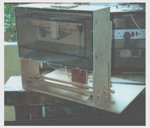
When a voltage is suddenly applied to the coil of the electromagnet, as happens when its associated key is pressed, the current rises exponentially from zero to a value equal to V/R, where V is the applied voltage and R the resistance of the coil. This is illustrated in Figure 2 (blue curve) for a heavy duty electromagnet supplied by a well known manufacturer of organ parts. In this case V = 15 volts and R = 30 ohms, thus the maximum current drawn was 0.5 amps, and the time taken for the current to reach this value was about 65 milliseconds. The reason for the relatively gradual growth of current is due to the associated magnetic field, which produces an opposing voltage known as a back emf as it increases in strength. At key release a similar situation pertains because it is not permissible to simply cut off the voltage supply suddenly. If this were to be done the rapidly collapsing field would produce a transient voltage over a thousand volts across the terminals of this particular magnet, more than enough to feel as a severe shock if one was foolish enough to be handling them at the time. Such a voltage would result in violent sparking at the key contacts if switched directly, leading to their rapid erosion. It would also lead to a risk of failure of the insulation of the coil windings over a period of time, leading to the magnet ultimately becoming useless. It would also destroy the transistors in a solid state switching system, either immediately or over a relatively short interval. Therefore the stored energy in the magnetic field must be enabled to dissipate more slowly, and the usual method is to connect a diode across the coil (see for example Figure 3); indeed diodes are supplied already soldered to the coils unless one requests their omission explicitly. A diode only conducts electricity in one direction, and it is of course connected so that it does not do so while the key contact is closed. But when the key is released the collapsing field results in a transient current through the diode which, however, thereby prolongs the decay of the field. The corresponding decay of the current through the diode is more or less a mirror image of the current growth when the note is keyed, and this is also shown in Figure 2 (purple curve). Thus the current through the diode is initially about 0.5 amps and it takes about 50 milliseconds to decay. Thus for this particular magnet the current decays more rapidly than it grows for reasons which need not concern us here, but the difference is significant in terms of its effect on release time as will be mentioned later. Note that both these curves were plotted from actual measurements on the magnet used for the experiments. Sometimes a Zener diode is connected in series-opposition with the ordinary diode; a Zener diode acts like an ordinary diode until the reverse voltage across it exceeds a certain value, at which point it conducts in both directions. Without going into a lot of detail, this technique can reduce the time taken for the field to decay while still quenching dangerously high voltages. However the maximum improvement possible for the magnet used for these experiments was about 20%, as discussed later. These results have illustrated the existence of an electrical inertia associated with large electromagnets, and it is interesting that for this magnet the growth and decay times are similar to the maximum allowable attack and release times for an action (62 msec) derived earlier. But in order to relate the data in Figure 2 to a practical action it is necessary also to investigate the part played by mechanical inertia due to the masses of the magnet armature, pallet and other moving parts. To do this it is simplest to make measurements on a complete action before we can say whether the action is sluggish. A test rig was built, illustrated below, although the magnet used for these experiments had an armature extension provided with a bush to which could be attached the pull down wire from a pallet, sketched in Figure 1 but not shown in the picture.
The pallet test rig This comprises two pallets, one of which is operated directly by means of a pull-down wire whereas the other incorporates various methods of touch relief such as a balanced valve. The latter are not described here but in another article on this site (see Touch Relief in Mechanical Actions). The rig was also used for experiments on pallet design, again not described here (see Calculating Pallet Size). Wind at about 300mm (12 inches) water gauge enters at the rear via a box fitted with an adjustable spill valve which enables the pressure to be set and automatically maintained at the desired level. Two water manometers are also at the rear, connected by PVC tubing to the input and output of the pallet. The front of the box is covered with perspex (lucite). Note that the pull down was attached to the pallet in line with the edge of the aperture remote from the hinge. The movement of the armature at the bush, and hence the pallet also, was about 7 mm and the initial force exerted by the magnet at the bush was about 320 gm. This force decreased as the armature moved towards the pole piece, a characteristic which is well matched to opening a pallet with pluck created by wind pressure. For this magnet in the configuration of Figure 1 to work, 320 ≥ Ap/2 + F where A is the area of the pallet aperture in cm2 ; p is the wind pressure in cm wg; and F is the restoring force in gm exerted by the pallet return spring measured at the bush. This relationship merely says that the magnet must pull the pallet with a force at least equal to the combined opposing forces of pluck due to wind pressure, plus the return spring force. The first term on the right, pluck, is divided by 2 because the pallet is hinged. Note that when speaking of a force measured in grammes as we did above, we are speaking loosely. Force equals mass times acceleration, and in this case the acceleration is that due to gravity (g), about 981 cm/sec2 . The equation above is correct provided all terms are regarded as mass, because g cancels out. In general, however, one has to be careful to include g in calculations of this sort otherwise major errors will ensue. Another trap for the unwary is that the density of the water in the manometer used to measure p would need to be included if units other than grammes and centimetres were used, in which system the density is 1 gm/cm3. The magnet was attached to a pallet covering an aperture 300 by 18 mm for which the value of F was measured at 107 gm. Thus the equation above enables a value to be calculated for the maximum wind pressure that can be used for this combination of pallet and magnet – it is 79 mm wg (3.1 in wg). This limiting value was measured experimentally at about 77 mm wg, a satisfactory agreement. A stabilised power supply was used for these experiments which maintained an output of 15 volts regardless of the load on it (note this is different to merely using a smoothed DC supply as is often done in organ building). The pallet was large and made of oak and thus it was pretty heavy (112 gm), the rationale for using it being that however the magnet performed with this pallet then it would do better with a smaller one. Attack Time for a Direct Electric Action An electronic method was used to measure the attack time of the configuration. As shown in Figure 1, electrical contacts were attached to the two felt armature end-stops such that circuits were completed when the armature was in contact with one or the other. These will be referred to as the On and Off contacts in what follows – the On contact was attached to the end-stop corresponding to the energised position of the armature, and the Off contact was attached to the other one.
The circuit in Figure 3 was used in which a flip-flop was set by a positive going pulse when the key was pressed, and reset by a negative going pulse when the armature reached the On contact. In this fully energised position the pallet was opened by 7 mm at the edge of the aperture. The use of a flip-flop eliminated problems due to contact bounce and thus multiple triggering with the simple contacts used, and the circuit could be arranged to respond to pulses of either polarity (positive or negative going) at both the set and reset inputs. The output of the flip-flop was therefore a pulse whose length was the same as the time between the key contact closing and the pallet fully opening. This pulse gated the output from an oscillator running at an accurately known frequency, and the number of cycles in the gated pulse was counted using an electronic counter. The oscillator frequency was about 11 kHz; the precise value did not matter as long as it was known accurately. The attack time of the action in milliseconds was therefore N / f , where N is the number of cycles counted and f is the oscillator frequency in kHz. Measurements of attack time were made for a range of wind pressures from zero to a value approaching the maximum permissible pressure (77 mm wg). Pressures were measured on a water manometer, and at each pressure several measurements of attack time were made so that a mean value and deviation could be calculated. Results are in the table below:
Several features are of interest:
One might expect the attack time to increase once an organ was in wind because of the additional pull required from the magnet to overcome pluck, making it necessary to wait slightly longer until the magnetic field strength reached the necessary level. But it is perhaps remarkable that the attack time then remained constant over a range of wind pressure until the magnet ceased to work reliably close to its operating limit. However a glance at the current growth curve in Figure 2 (blue curve) shows that the current, and hence magnetic field, reaches 80% of its final value within about 30 msec for this magnet. Therefore differences in values of pluck would have a relatively small effect on variations in attack time because of the nature of exponential curves, which rise quickly at first then slow down later. Nevertheless the result is counter-intuitive to some extent, which demonstrates the importance of performing careful measurements. It is purely a happy coincidence that the attack time of this direct electric action (60 msec) just betters the requirement for a repetition capability of 8 per second according to the earlier analysis, in which an attack time of not greater than 62 msec is required. Release Time for a Direct Electric Action These measurements used a different arrangement for setting and resetting the flip-flip circuit to achieve a measurement of the time between the key contact being broken and the magnet armature regaining its rest position.
The circuit in Figure 4 was used, in which the flip-flop was set by a negative going pulse when the key was released, and reset in the same way as before but this time using the Off contact. Results for a range of wind pressures as before were:
That the release time was smaller than the attack time was, on the face of it, a surprising result. For the net accelerating force acting against the inertia of the armature and pallet during attack was 213 gm once the pluck had been broken (magnet pull minus spring tension), whereas during release the restoring force was only that of the return spring (107 gm, almost exactly half). However the magnet pull during attack reduced dramatically with armature travel, and the electrical rise time was greater than the decay time during release. These two factors contributed to this result. But in view of this it was also of interest to measure the release time of the action from an un-energised magnet, that is, one in which there was no magnetic field to decay. Therefore in this case we would be measuring the release time resulting purely from the mechanical inertia of the action. Although this would not occur in practice, by comparing the figure with the results above it might demonstrate the proportion of the release time which was attributable to the decay of the magnetic field through the use of a spark suppression diode.
To do this the two contacts on the end-stops were connected in parallel and simply used to gate the oscillator signal directly as in Figure 5. No current was supplied to the magnet, which was merely held open manually against the pull of the pallet return spring. It was then released, and during the inertial transit of the armature between the two end-stops the number of cycles of the oscillator frequency were counted electronically. No wind pressure was used. The release time in this case was 38.6 ± 3.3 msec, which (from the table above) is about 20% less than the corresponding figure for the release of a previously energised magnet. This implies that the decay of current through a spark suppression diode adds about 20% to the purely mechanical release time of the action. If a Zener diode was to be connected in series with the ordinary diode, as discussed earlier, this result means that the maximum possible improvement in release time for this action would be limited to about 20%. In practice it would be less. This is rather more sober than the claims made by some organ builders for a "stunning" improvement in response by the use of this technique (see, for example, [1]). Repetition Capability of a Direct Electric Action We ought now to be able to predict what the repetition capability of this action should be. We know that the attack time is 60 msec and the release time 47 msec, both independent of wind pressure over the range for which the magnet will work. Adding these times together should give the minimum possible repetition period for this particular action when a note is keyed repetitively, this figure being 107 msec. The reciprocal gives the maximum repetition frequency at which the action should work, 9.4 per second in this case. Therefore the action should satisfy comfortably our musical requirement for a repetition capability of 8 per second. It is instructive to confirm or otherwise this prediction by discussing repetition measurements on the action.
Referring to Figure 6, a frequency divider was used to generate a periodic repetition frequency from a higher frequency which could be measured accurately, a division ratio of 1024 being used. The output of the divider was applied to an electronic relay which switched the magnet on and off with negligible extra time delay. At each setting of wind pressure an initially high applied frequency was decreased until the magnet armature and pallet just began to execute full excursions in both directions. Results are below:
The value of 1.5 Hz for a wind pressure of 77 mm wg can be ignored, because at this pressure the magnet is only marginally capable of opening the pallet against pluck. At the minimum pressure used (52 mm wg) the repetition frequency was slightly better than that predicted above. But at the other pressure values we see that the maximum repetition frequency the action can support decreases markedly as the pressure increases. Given the foregoing static measurements of attack and release times this is a most surprising result. How can this variation exist when the previous measurements were independent of wind pressure? The magnet should not "know about" the wind pressure it is acting against! In fact the answer to the conundrum is complex, but it demonstrates that one cannot make predictions about the dynamic behaviour of a system based on static measurements alone – this is true across all of physics and engineering. To emphasise this further let us note a hysteresis effect observed when doing the experiment: the repetition values in the table above were obtained by reducing the frequency from a high value until the action oscillated reliably. But conversely, if the frequency was increased from a low value until proper operation ceased, that reading was significantly higher. This effect was probably due to remanent wind pressure building up in the groove above the pallet as the frequency increased, together with remanent magnetism in the magnet core. Neither pressure nor flux did not have time to completely die away each cycle as the frequency increased. Thus once the oscillation had become established, the magnet was working against a lower value of pluck than the static wind pressure setting would imply, together with an amount of remanent flux which assisted the magnet to pull in during each cycle. But the main reason for the unexpected results in the table was due to the winding and regulator systems used, which were under-damped. Thus whenever a sudden change in wind demand occurred caused by the pallet opening or closing, there was a transient overshoot in wind pressure. Under these conditions the action was working against actual wind pressures which were different to those set statically before each measurement was made. When the pallet closed suddenly a pressure overshoot arose which did not always have time to dissipate before the pallet was required to open again. At static pressure settings above about 60 mm wg this overshoot exceeded the operating limit of the action (77 mm wg). Consequently in these circumstances the action had to wait until the pressure reduced to a value at which the magnet could open the pallet, and this effect reduced the apparent repetition frequency at higher static pressures. It is however gratifying to note that the action itself worked generally as predicted and as required – in the absence of excessive pressure overshoot (for example at a static pressure setting of 52 mm wg) the action could support a repetition frequency of 10 Hz. This is not far away from the prediction of 9.4 Hz, and well in excess of the requirement for 8 Hz. Summary – direct electric actions The main outcomes of part 1 of the paper are:
Although the work described so far has gone a long way in establishing the performance of direct electric actions it still does not enable a definite answer to be given to questions such as "yes, but is an electro-pneumatic action better?" This brings us to the next instalment of this gripping saga.
Part 2: Electro-pneumatic Actions The main practical problem in trying to establish the performance of electro-pneumatic actions is their diversity – almost every organ builder who has used them has introduced his own variations.
A representative action is sketched in Figure 7; here three stages are used although the intermediate pneumatic relay (also known as the primary pneumatic) might be omitted occasionally if the pallets are small. It may also be combined with the chest magnet, as in Kimber Allen's Compound Magnet range. When it exists separately, some builders equip it with a return spring as shown whereas others do not; some invariably build the action in the form of power boxes which fit under the chests and which can be supplied with wind at a higher pressure, whereas others incorporate the action within the soundboard whenever possible. These and several other factors are vitally important when drawing conclusions about the performance of an action. About the only matter which remains the same across most actions is the use of proprietary chest magnets, and in this study a very widely used unit was employed from the same supply house as the heavy duty magnet discussed already. A chest magnet designed to work on 15 volts has a resistance of typically 170 ohms, so it consumes less than one fifth of the power of the heavy duty magnet used previously. It only has to move a small disc armature a couple of millimetres or so to allow the intermediate pneumatic relay to exhaust or re-inflate. The intermediate relay is used because the small orifices in the chest magnet would throttle the passage of air if the main power motor worked directly through them, thereby slowing the action down. It is the most critical element of the system as far as design is concerned – if too small it will be unable to work valves large enough or quickly enough to allow unrestricted passage of air for the power motor. If too large it will itself be throttled by the chest magnet, and it would add excessive inertial time delay to the action both during attack and release. The growth and collapse times of air pressure in both the relay and power motor are analogous to the growth and decay of magnetic flux in the heavy duty magnet, and these times are controlled largely by the sizes of the relay and its valves. Thus unless the optimum size of relay is used the action will be unnecessarily slow. If the power motor is contained in the main wind chest it must have a surface area larger than that of the pallet aperture so that it is able to overcome pluck plus the return spring tension. Therefore it will turn out to be at least the same size and mass as the pallet itself, with undesirable implications for inertia and hence response time. These disadvantages can be relaxed if the motor operates at a higher wind pressure than the pallet, though the gains are less than might be imagined – the smaller mass of a smaller motor reflects into response time as the square root. Therefore reducing the mass by a given factor only reduces response time by the square root of that factor. In analysing the behaviour of electro-pneumatic actions a combination of experimental measurements and theory will be employed to overcome the difficulties posed by their diversity. Attack time for an electro-pneumatic action Measurements were made of the attack time of a typical commercial chest magnet in the same way as before – an electrical contact (the On contact) was used which enabled the response time to be measured electronically. Because the face of the armature which was pulled towards the magnet was of plain metal, a simple contact was attached to the magnet assembly which engaged with this face when it reached the magnet poles. The magnet would pull in over a wide range of wind pressures, so measurements were made at widely different values. Using the measurement system sketched in Figure 3 a few typical results are shown below:
As for the heavy duty magnet the attack time increased once the wind was applied, but in this case it continued to increase with increasing pressure. However note the pressure range shown above is about double that which the heavy duty magnet plus its pallet would tolerate. It is not surprising that for such a small assembly the response time is so rapid, in all cases below one hundredth of a second. For the purpose of this study a value of 8 msec was used in subsequent analysis. It is easiest to derive results for the power motor from theoretical considerations, as these then enable a wide range of configurations to be evaluated. The motor and pallet have to be considered as a whole since they are rigidly coupled, and by considering moments of inertia of the system the attack time can be calculated. The details will not be included here as this paper is already so long, but the salient features of the simplest possible analysis are:
In the simplified analysis no account was taken of friction, lost motion, the resistance of the leather to motor movement, the work done to overcome pluck, the work done in expelling air from the motor nor any throttling effect which might occur in the relay valves. Thus the attack time derived from it must be taken as an irreducible lower bound, which in practice would be exceeded in a real action. To compare the value of attack time with that for the heavy duty magnet considered previously, the same parameters were used. Thus d = 7mm, power motor force = 320 gm, spring force = 107 gm and pallet mass = 112 gm. The power motor mass was also taken as 112 gm as it will typically be about the same size as the pallet and made of similar material. With these values an attack time of 23 msec was predicted. A typical relay motor would be circular with a diameter of about 36 mm and it would be required to move the valves by about 3 mm. Using these values together with others representing typical return spring force and the masses of the components, an attack time of about 15 msec results. This value will be used in subsequent stages of the analysis. On the face of it therefore, the total attack time for a typical electro-pneumatic action is the sum of the chest magnet response time (here taken as 8 msec), the intermediate relay time (15 msec) and the power motor time (23 msec), giving a total time of 46 msec. Objections might be raised that simple addition of these times is not permissible since this implies that each element of the action waits until the previous one has completed its movement before beginning to respond. However the error is probably not large as each element has to accelerate from rest while the previous one is still in the process of opening its control valves. It is not proposed to make an allowance for this factor because we have already used a value for power motor response which is unrealistically low, so the two effects will compensate to some extent. This value of 46 msec compares with the value of 60 msec measured for the heavy duty magnet under the same conditions, so in this case it is true to say that an electro-pneumatic action is faster in attack than a direct electric one. Discussion of whether the difference is relevant will be deferred until after the release times have been compared. Release time for an electro-pneumatic action Measurements were not made of the release time of the chest magnet as it was assumed to be the same as the attack time (8 msec). Even if there was a difference it would only alter the total release time of the action by a few milliseconds either way. Similarly, the release time of the relay was assumed to be the same as the attack time (15 msec). In this case we are probably being charitable, because the relay when released will accelerate either under the action of a spring or even merely its own weight, depending on the design of the action. By contrast the attack time arises from a constant pressure difference across the motor which creates a force at least equal to pluck plus spring tension plus motor weight. So a release time of 15 msec is probably an under-estimate. As with the relay, the power motor re-inflates solely under the restoring force of the pallet spring which also has to accelerate the pallet. Here the release time can be calculated as before using all the same parameters except for accelerating force (F). In this case F is the spring force, 107 gm in this example. The release time turns out to be 32 msec, but note as before that this is a lower bound because the effects of friction, etc are not included. This is similar to the measured release time of the un-energised heavy duty magnet at 38.6 msec (i.e. when the armature was released manually). The correspondence is gratifying because the two systems when compared under these conditions were similar in mechanical characteristics. The direct electric system consisted of a 112 gm pallet coupled to the substantial magnet armature, both returning under the influence of a 107 gm spring force, and the result was obtained experimentally. The electro-pneumatic system consisted of the same pallet coupled to a motor with the same mass and returning under the same spring force, but the result was obtained theoretically. If the discrepancy had been large the validity of the theoretical result would have been thrown into doubt. Adding together the three contributions to the release time as before, we arrive at a total time of 55 msec. Again as before we assume that the various uncertainties in this estimate will mutually compensate to some extent. This time the result exceeds that for the direct electric system, in which the release time was 47 msec, therefore this particular electro-pneumatic action releases more slowly than the direct electric one. Repetition capability of an electro-pneumatic action For the heavy duty magnet we added the attack and release times to arrive at a predicted figure for repetition capability which was confirmed experimentally (when other factors such as inadequacies in the winding system were identified and allowed for). Doing the same in this case gives a total time of 101 msec, which should lead to a maximum repetition frequency of 9.9 Hz. This is virtually identical to the predicted value of 9.4 Hz for the direct electric action, and its measured value of 10 Hz. Summary – electro-pneumatic actions The main outcomes of part 2 of this paper are:
Unlike the corresponding figures for the direct electric action which were all obtained experimentally, those in this case relied heavily on theoretical modelling. Useful validation of the results is mentioned above (in 5), from which it is possible to say that the results cannot be in error by a large factor. For example a factor of 2 discrepancy could not be entertained otherwise the result in 5 would not have been obtained, thus any error has to be much less than this. Consequently it is reasonable to use these values to compare the performance of an electro-pneumatic system with a direct electric one. It would be perfectly feasible to make measurements of the response speed of any given electro-pneumatic action using techniques similar to those described in part 1, and these would be useful for organ builders who have standardised on a particular action design. But because of the wide diversity of such designs single measurements would be of little value in being able to make predictions about others. The use of theoretical modelling gives more flexibility in this regard, and it could therefore be used to optimise the performance of any given action. Before drawing together the conclusions of this work it is useful to tabulate again the main assumptions and outcomes for convenience in the discussion. For both direct electric and electro-pneumatic actions the same parameters were used, both when measurements were made on an action and when it was modelled theoretically. The parameters were:
The main outcomes of the work are summarised below:
Because a direct electric action can be made which comfortably exceeds the required repetition performance of 8 Hz there seems little foundation for the belief that direct electric actions are always intrinsically "slow". Moreover an electro-pneumatic action is not likely to do any better. We should note again that the pallet used in these experiments was relatively large and heavy and representative of one which might be used for the bass notes of an organ. Higher in the compass the pallets would be smaller and lighter and so they could be expected to respond even more rapidly. The perceived sluggishness of direct actions might therefore have arisen from other factors such as:
Should direct electric actions be used in conjunction with mechanical actions? If there are two consoles, one mechanical and the other direct electric, this paper has shown the latter could provide adequate repetition performance provided the mechanical inertia of the action attached to the magnets was not excessive. It would be unwise to place the magnets at a distance from the chests so that they had to overcome the inertia of the tracker work as well as the pallets. Using heavy duty magnets to assist the coupling or to open auxiliary pallets could introduce noticeable delays between the mechanical and electric elements of the action, depending partly on the responsiveness of the mechanical action itself. However on the basis of the results obtained here it is debatable whether these would be any worse than with electro-pneumatic helpers. In conclusion let us return to the quite reasonable question as to which is the better action – direct electric or electro-pneumatic. The results presented here are inconclusive in this regard only because the two types appear to perform similarly. But one thing they show unequivocally is that direct electric actions can work faster than the demands likely to be placed on them by the performer, just as can electro-pneumatic actions. Since direct actions are cheaper it is not surprising their cost-effectiveness often makes them the system of choice. 1. Letter to the editor, P Burns, Organists' Review, p. 173, May 1999. 2. Letter to the editor, A Wadey, Solid State Organ Systems, Organists' Review, p. 73, February 2000. |