


|
|
The Electronic Reproduction of Very Low Frequencies by Colin Pykett
Posted: May 2004 Last revised: 3 February 2015 Copyright © C E Pykett
Abstract The majority of electronic organs are sadly deficient in the way they reproduce extreme bass notes because the provision of the necessary loudspeaker system would add substantially to their cost. This annoys many owners of such instruments which often boast 32 foot pedal stops, but whose effects progressively vanish towards the bottom of the compass! This article explains why extreme measures have to be taken to reproduce extreme bass, regardless of the claims often seen in advertising material and elsewhere. However it suggests some relatively simple and inexpensive ways in which the bass response of an electronic organ can be improved. This article was first published in a specialist journal in 1985, and in modified form it was made available on this site in view of the continuing interest in low frequency reproduction for electronic organs, particularly using a genuine near-infinite baffle. A number of such installations have been made by myself and others over the intervening years.
Contents (click on the headings below to access the desired section)
A Physical Picture - Size Matters, or Big is Beautiful
What is the best system - an Infinite Baffle?
The Effect of the Listening Room
The requirement to radiate acoustic energy at frequencies down to at least 30 Hz in a small room causes problems for those who have a penchant for organ music, either reproduced or played on an electronic instrument. While proper reproduction of the Sydney Town Hall organ demands a house-rattling capability down to 8 Hz, I shall be more reasonable in this article by setting 30 Hz as the lower limit (corresponding approximately to the frequency radiated by a 16 foot open organ pipe - bottom C on the pedals). This is difficult enough but if you can achieve it, extrapolating downwards to 16 Hz for 32 foot stops becomes easier, at least in theory. There are two major problems to address, of which one is the loudspeaker. Few of the cheaper commercial electronic organs can radiate 30 Hz efficiently and without harmonic distortion, and this is particularly important for quiet flue stops such as Bourdons. The soft unforced quality of the bass which one hears from such pipes in a large building is peculiarly difficult to capture with electronic reproduction. These pipes have few harmonics above the fundamental, therefore it is essential to be able to radiate the fundamental frequency itself. If this is attenuated because of excessively inefficient loudspeakers, the ear will not reinsert it as commonly supposed. When there are so few harmonics, all of them at frequencies where the sensitivity of the ear is low, this oft-quoted psychological phenomenon does not occur. The ear does compensate to some extent for a missing fundamental when there are many harmonics of high amplitude, such as with a loud pedal reed which typically may have over a hundred. However this is a different matter to the quiet flues which have perhaps three or four of rapidly diminishing amplitudes. The so-called sub-woofers commonly used in home cinema or in-car entertainment systems are likely to be useless for organ or serious hi-fi work. Most of the time they are only called upon to radiate transients such as drum notes or the bangs and crashes inseparable from movies such as Jurassic Park. Such programme material is different in kind to that from an organ. In fact many sub-woofers are highly resonant at frequencies above our 30 Hz figure, and these resonances are merely excited whenever signals arrive of the sort mentioned above. When a dinosaur is rampaging through a primeval forest on the screen, it does not really matter whether the associated sounds are radiated with high fidelity or not. Similarly, when youngsters cruising around in cars advertise their presence with the high intensity drum beats which they seem to enjoy, it does not matter whether the spectral character of the original material is modified by extreme loudspeaker resonances. Who would know or care? Yet playing an electronic organ or an organ CD through such a loudspeaker system can be disappointing – the fundamental frequencies of the lowest notes are simply not there, and there may be some ridiculous emphases of other frequencies. The term "one note bass" is sometimes used to describe loudspeakers such as these, because they really only give an illusion of powerful bass by radiating at the resonant frequencies of the system. Such loudspeakers are entirely inappropriate for serious musical use. They can make a lot of noise, but often the noise has no affinity with the high fidelity required for reproducing organ music in a way which will satisfy an educated musical ear. The second major problem is caused by the room you are listening in. Contrary to popular belief, the acoustic response of real rooms at low frequencies cannot be modelled easily, if at all. Thus widely discussed parameters such as 'room gain' and 'modes' are equally widely misunderstood, and the only way to approach an understanding of what a room does to a loudspeaker is to actually measure its response. All these matters are discussed in the article.
Loudspeaker system design in this frequency region is complicated by the fact that not only is the response of the loudspeaker falling off (typically by at least 12 dB per octave, sometimes more) but so also is that of the ear. Thus subjectively satisfying bass reproduction may involve acoustic powers of several watts compared with milliwatts elsewhere in the spectrum (Figure 1). While the provision of sufficient electrical power is no longer a problem as it used to be in the days of valve (tube) amplifiers, the satisfactory conversion of it into acoustic power is still not easily solved.
Figure 1. Responses of the ear and of a "good" hi-fi loudspeaker This article attempts to derive a clear view of the physics of the situation with a promise of no maths, jargon or other mysticism. Having established the physical picture, some common loudspeaker designs are discussed followed by some observations and recommendations based on personal experience. I hope this will open up a way ahead for those who feel they have yet to reach their low-frequency Nirvana
It is unfortunate that loudspeakers, probably more than any other component in the reproducing chain, have been the focus of misunderstanding, myth and downright nonsense even among those who should know better. For example, journals which claim to be reputable have devoted space over many years to garbage such as the "advantages" of grossly expensive speaker cable over much cheaper ordinary material, while ignoring the very real detrimental effect of the contact resistance of flimsy connectors (e.g. of the DIN variety) and of in-line fuses within the amplifiers which are quite unsuited to the heavy currents involved. At high currents the latter, and often the former, behave as nonlinear circuit elements whose resistance varies with current, leading to distorted sound at all frequencies, not just the low ones. Another phenomenon is that we are expected routinely to defer to pundits who claim that one loudspeaker design or another is so effective that all others are an irrelevance. Yet meaningful data are seldom produced to support their remarks. It is salutary to keep in mind Lord Kelvin’s deservedly famous dictum that "when you cannot express it in numbers, your knowledge is of a meagre and unsatisfactory kind". Without careful and time-consuming measurements made in the actual room in which a loudspeaker is situated, exaggerated claims about its performance can be nothing more than qualitative and subjective gobbledygook. This is true regardless of the bluster and arrogance of the material one encounters, and of its quantity or the eminence of its author. So often such people reveal themselves merely as "loud speakers". Thus, although this article is written largely at a non-technical level, you will find such measurements are presented at the end for a system which I incline to myself. As a result of this widespread pseudo-scientific situation a number of myths continue to circulate. Some are listed below; all are either untrue or only true within certain caveats:
How many of these do you subscribe to?
A Physical Picture — Size Matters, or Big is Beautiful A rigorous analysis of the loudspeaker and its enclosure treated as an electro-acoustic transducer system is not fundamentally difficult in a mathematical sense but it involves some long-winded algebra, and (worse) tends to obscure the simple picture of how a moving object in the air (a loudspeaker cone) causes acoustic energy to propagate away from it.
Consider a normal moving-coil loudspeaker mounted behind an aperture in a thick piece of wood (a baffle) about 10 metres in diameter. This is a large object, about the height of a two storey house, and it approximates to a true infinite baffle down to very low frequencies indeed. In spite of its inconvenient size, it is nevertheless a useful starting point for the discussion. Because of the low frequency assumption we can be confident that the loudspeaker cone moves to and fro as would a rigid piston in response to an impressed sine wave without breaking up into various regions moving in different directions, a phenomenon which occurs at higher frequencies. Consequently when the cone moves forward, air in front is compressed. That at the rear is rarefied, and the air pressure attempts to equalise itself by moving around the edges of the baffle. Since in this case the baffle is large, the time taken for these equalisation movements is also large (limited by the speed of sound, which is the fastest that pressure waves can travel). For a 10 metre baffle, the time taken for a pressure increase at the front of the cone to reach a corresponding point at the rear is about 30 msec. Since frequency is the reciprocal of time this corresponds to about 33 Hz, a fact which shows that below this frequency there will be time for the air pressure to substantially equalise as the cone moves, thereby reducing the amplitude of the pressure changes which propagate to the listener who interprets them as sound. Thus low frequency reproduction demands a large baffle, an inescapable fact, though a more detailed analysis backed up by practical experience shows that 10 metres is a bit excessive for 30 Hz and 3 metres would be quite good. Even this, though, is domestically inconvenient. We have not yet finished deriving our simple physical picture. If baffle size was all that mattered for bass reproduction then it might be imagined that a 65 mm (2½ inch) tweeter ought to be as good as a 450 mm (18 inch) woofer. This is plainly not so, though the influence of cone area on bass reproduction is less well understood than the effect of a baffle. It is loudspeaker size that we shall now explore. Assume there is a truly infinite baffle (so that pressure equalisation effects do not occur) and imagine what happens to the air in front of the cone as it moves forward. Initially, the cone compresses a cylindrical column of air in front of itself. Immediately, the local pressure enhancement within the column is dissipated by air movement from inside to outside the column, leading to propagation of a disturbance which causes the sensation of sound. Intuitively we may see that the wider the column (i.e. the larger the loudspeaker) then the longer the equalisation process will take, because a high pressure area in the middle of a fat column has further to move before it dissipates within the atmosphere at large than if it was in the middle of a thin column. This dissipation time governs the time for which outward sound propagation from the loudspeaker will occur in response to a cone movement and hence the amplitude of the disturbance at a given distance from the speaker. Thinking further, it is possible to deduce that for efficient radiation of a particular frequency, the dimensions of the loudspeaker cone should be some appreciable fraction of a wavelength. If it is not then pressure dissipation, at the speed of sound, will take place in too short a time for the frequency being radiated. This is a fundamental requirement for all structures, whether acoustic or electromagnetic, which have to launch a disturbance into the environment efficiently. Therefore it also applies to real organ pipes which (in the case of flue pipes) are never less than a quarter of a wavelength long. In the case of loudspeakers a diameter corresponding to, say, half a wavelength at 30 Hz would be about 5 metres. Again, experience shows that this is not really required but, as for baffles, the bigger the better. Certainly an aperture one tenth of this, corresponding to a large 450 mm (18 inch) loudspeaker, is getting a bit marginal at 30 Hz. Therefore we have a second important truth: the size of the loudspeaker unit itself must be as large as possible to radiate low frequencies. It need not be a single loudspeaker - a number of smaller units wired in phase is just as effective as a single one of the same total cone area and they may be a lot cheaper. The mathematics shows that nature unexpectedly favours our endeavours regarding loudspeaker size in that radiating efficiency at low frequencies is proportional to the square of the cone area. Thus two loudspeakers close together are four times as effective as one of the same size at low frequencies.
It is accepted wisdom that the resonant frequency of a loudspeaker should be as low as possible for good bass reproduction. This is true but at first sight it may not be obvious why - after all, any moving coil loudspeaker plainly has a response down to "DC" since a battery connected to the terminals will cause the cone to move to a new position and stay there until the voltage is removed. The resonant frequency is determined principally by the mass of the moving elements (cone, etc) and by the stiffness of the suspension system, which incorporates a form of spring. Low stiffness and high mass contribute to the desirable low resonant frequency. Below resonance, the loudspeaker frequency response is dominated by stiffness. We can see this in the above case where the cone moved in response to an applied voltage step. The weaker the spring, the more the cone will move for a given current through the voice coil. (Above resonance, the response becomes mass-dominated, because at these higher frequencies the forces required to accelerate the cone become progressively higher. Note that this behaviour is analogous to that of an electrical tuned circuit where the impedance is capacitive below resonance and inductive above. Capacitance and stiffness represent methods of storing potential energy; inductance and mass are best regarded as reservoirs of kinetic or motional energy). Extended bass response implies large cone excursions at low frequencies, hence low stiffness in the suspension, which is in turn reflected in a low resonant frequency. QED. Incidentally, the term compliance is often used instead of stiffness in loudspeaker documentation. The two are reciprocals of each other.
We shall begin our survey of loudspeaker enclosures by looking at the hermetically sealed box, represented by the ubiquitous "bookcase" loudspeaker. This enclosure (Figure 2) is an approximation to the infinite baffle in that it prevents pressure waves from the rear of the cone cancelling those from the front. A typical sealed box design has the loudspeaker mounted off-centre in one wall, and absorbent wadding inside to reduce resonant modes due to reflections from the inner surfaces. However, unless the box is extremely large, it is most definitely not like the true plane baffle of large dimensions that we considered earlier. This is because the movement of the cone results in compression and expansion of the enclosed air, which gets hotter as a result. Thus the amplifier has to deliver extra power to heat the air and, for a given input level, less power is radiated as sound. At low frequencies, an additional aspect of inefficiency also comes into play: this is due to the air loading on the cone, raising the resonant frequency of the loudspeaker by virtue of its stiffness or resistance to compression. We have just seen why this will reduce the radiating efficiency at low frequencies below resonance. (For this reason the suspension of a loudspeaker for use in a sealed enclosure is sometimes very "floppy", so that when in the box a proper value of stiffness is restored by the air loading). Sealed enclosure design to achieve good bass response is seldom as effective as the advertisements suggest. The story goes that by making the loudspeaker cone able to execute large movements, adequate bass response can be achieved at the expense of the efficiency of converting electrical into acoustic power. To a degree this is true, but the principal limitation (aside from the very real danger of overdriving the loudspeaker with high-power long pedal notes on the organ) is that harmonic distortion occurs owing to the voice coil moving through a not perfectly uniform magnetic field during its excursion. Distortion also occurs owing to the nonlinearity of the environment against which the cone moves - as the air in the box is compressed and expanded adiabatically (which means faster than the resulting temperature changes in the air can dissipate), the force required to move the cone changes nonlinearly with respect to cone excursion. Such distortion results in audibly impure bass for organ work, though the system is perhaps generally acceptable for other types of programme such as tympani transients. Notwithstanding this, though, I have yet to come across a commercial sealed box loudspeaker which is adequate, to my ears, at 30 Hz or below.
A reflex enclosure (Figure 3) is similar to the sealed box except for the presence of a port close to the loudspeaker. The port is usually the aperture of a pipe which extends back inside the box. The air in the box and port has mass and springiness and thus both can resonate at particular frequencies. The loudspeaker unit itself also has its own intrinsic resonant frequency. The trick in bass reflex design is to juggle these resonant frequencies so that, at low frequencies, the pressure waves from the rear of the cone emerge through the port in phase (not in opposition) with those from the front. This is not an easy thing to achieve because of the criticality of the adjustments (Q factors are surprisingly high at these low frequencies for those of us brought up on a diet of resonance in lossy electrical circuits). This makes it necessary to adjust each cabinet to the characteristics of the drive unit actually used, because loudspeakers often seem not to embrace close tolerance construction. Therefore simply building a reflex cabinet from a published design will not automatically provide good bass no matter how careful the original calculations were. There also has to be very effective sound absorption inside the box at frequencies above, say, 70 Hz otherwise the response at higher frequencies will be seriously affected. With all these difficulties, what advantages are conferred by the bass reflex system? Firstly the efficiency is higher than for the sealed box because the energy from the rear of the cone is used rather than being dissipated as heat. It is also possible theoretically to extend the bass response below the resonant frequency of the loudspeaker unit, but this is only practicable with large enclosures. Nevertheless the reflex enclosure does not affect the resonant frequency of the loudspeaker unit itself so adversely as does the sealed box, even for a small reflex cabinet My experience is that bass reflex enclosures are fine in theory but can be disappointing in practice. I once spent hours using probe microphones to carefully adjust a 0.23 m3 (8 cu ft) cabinet containing a 300 mm (12 inch) loudspeaker and obtained a reasonably flat response down to about 40 Hz, but this was a bit disappointing for such a large box. For organ applications you have to remember another shortcoming of the reflex enclosure, which is that the response really does rocket off at the bottom end: 18 dB per octave compared with around 12 dB for most other forms of enclosure. Thus my cabinet, fine at 40 Hz, was significantly less effective at 30 Hz. Do not assume that the bass reflex enclosure is an old fashioned scheme seldom used nowadays. Commercial designs using the so-called auxiliary bass radiator (ABR) are the reflex enclosure in a modern guise. The ABR is placed in the port, being similar to the cone and suspension system of a normal loudspeaker. Its characteristics enable a lower resonant frequency to be obtained from a relatively compact pipe and cabinet. However, small reflex enclosures are more critical to adjust than large ones, and the presence of the ABR makes things one stage more difficult (quite apart from the additional harmonic distortion produced by possible nonlinear effects in the ABR, which may have cone excursions quite as large as those of the loudspeaker itself). Thus only the most expensive loudspeakers of this type having a frequency response curve supplied can be relied upon to fulfil their brochure promises. I did once invest in a pair of hi-fi speakers of this pedigree comprising a 200 mm (8 inch) bass unit with a somewhat larger ABR, and today they retail at over £1000 a pair. The major cabinet dimension was about 760 mm, yet even from this structure the bass response (from the curve supplied) began to fall off rapidly at 50 Hz. This is not a criticism of the loudspeaker as such: it only demonstrates that you simply cannot get extreme bass from objects of this size no matter how expensive they may be. I still have these units (you do not just throw such things away!) and they are very acceptable for general hi-fi use, but far less so with organ recordings and the lower pedal notes of an electronic organ. Probably the most absurd misunderstanding about bass reflex cabinets is demonstrated by the aperture of the port in most designs. Usually it is only a small fraction of the diameter of the woofer itself. We have already discussed why the cone area of a low frequency loudspeaker must be as large as possible to achieve as high a radiating efficiency as possible, and this applies equally to the port. A port which is only a couple of inches in diameter is no more effective in reinforcing the low frequencies than a tweeter of the same size would be, as far as aperture size alone is concerned. It defeats me to understand why this fundamental and completely daft mistake is made so often in commercial designs. Because of this, units which use an ABR are usually a better bet because the area of the ABR is generally comparable to that of the woofer. You can do a quick but rather crude check to see whether the port in your reflex enclosure does actually enhance the low frequency response, provided you have some sort of sine wave signal generator that goes down to the necessary low frequencies. Set it to the lowest frequency you can hear from your speaker and then cover up the port with some object such as a saucer. If the sound disappears completely then the enclosure is obviously extending the LF frequency response of the cabinet. However, quite often commercial reflex enclosures do not operate in the reflex mode at all yet they will still pass this simple test. This is because they are badly tuned and instead they are resonating at a single frequency just as though they were a sealed box. But in this case the presence of the port lowers the Q of the resonant peak because energy is allowed to leak out of the box, which flattens the frequency curve somewhat and makes it extend a bit further below resonance. This means more energy is radiated from the skirts of the response below the resonant frequency than if the box was completely sealed. But this does not necessarily mean the cabinet is operating in reflex mode. The only way to check whether a bass reflex cabinet is working properly is to look for its resonance peaks - there should always be two of them and their heights should be about the same. However this is taking us into the realm of specialist measurement and we cannot delve further into the subject here.
A horn (Figure 4) is a flared tube whose diameter at one end corresponds to that of the loudspeaker used as a drive unit, and at the other it is as large as can be comfortably accommodated. In practice the tube might be folded to conserve space. By gradually increasing the width of the horn the relatively stiff cone is matched gradually into the outside world consisting of the tenuous air. This acoustic transformer effect occurs because the progressively widening air column exhibits a progressive acoustic impedance change along its length. Thus there is a better impedance match than would be the case for the drive unit radiating directly into the room. This enables greater acoustic powers to be achieved with a given electrical drive level, but only within the frequency region for which the horn has been designed. The so-called horn cutoff frequency defines the lowest frequency for which "horn action" will occur. It really disguises the fact that the mouth of the horn is a radiating aperture just like a normal loudspeaker mounted in a baffle, and we have already seen how bass response depends on the size of the aperture. A horn cannot be flared too rapidly or it ceases to act like a horn. The flare usually follows an exponential or similar curve, and this limits the aperture of many designs to an area roughly equivalent to a 400 mm diameter cone if the horn is to be constrained to a length suitable for a domestic room. Consequently the bass reproduction of such a horn will be little better than a single directly radiating 380 mm (15 inch) loudspeaker, and worse than two 300 mm (12 inch) units driven in parallel. The issues of efficiency and drive level for horns need to be explored a little further. With horn sizes that would fit in an average domestic room it is unlikely that the horn cutoff frequency will be as low as we would wish, remembering that 30 Hz is our target figure. Therefore at these low frequencies the horn would quite likely not be acting like a horn in an acoustic sense, thus the acoustic transformer effect will be degraded or non-existent. This could mean that a small driver unit at the throat of a horn might have to move a volume of air equivalent to that which would be moved by a larger loudspeaker of equivalent area to the mouth. Consequently the little driver may have to work very hard in terms of cone excursion and therefore it may generate more distortion than the larger direct radiating loudspeaker. It must be remembered that, for horns, the virtues of increased efficiency and better bass response only refer to the size of loudspeaker used as a driving unit above the cutoff frequency: if a horn is driven with a 125 mm unit and has an aperture equivalent to a 400 mm unit, then certainly the efficiency and bass response of the small speaker is enhanced to approximate that of the larger one. However below cutoff the combination of such a horn and driver is no more effective than a single 400 mm direct radiating loudspeaker in a suitable cabinet would be, and may well be worse in terms of harmonic distortion (I will not at this juncture define what might constitute a "suitable cabinet", I only would point out that it is likely to be less complex and less domestically objectionable than a horn). The conclusion is that horns are only sensible where advantage can be taken of the cone area magnification effect to achieve an equivalent area to an otherwise unattainable loudspeaker or loudspeaker array. In these circumstances the horn will be truly enormous, suitable only for concert halls and the like. Even those manufacturers of electronic organs who say they always insist on the provision of a horn are sometimes found to have compromised in practice, when a bass reflex enclosure is discovered. If a church or a cathedral is not big enough to house a horn, what building would be? The lingering penchant for horns in a domestic environment, it seems to me, is a hangover from the days (specifically, the 1930’s) when it was not easy to obtain large, good quality direct radiating loudspeaker units and it certainly was not possible to drive them with more than a few watts of electrical power.
There are several other types of loudspeaker enclosure that might be discussed but none are particularly notable for their extremely low frequency performance. One enclosure allows the front of the loudspeaker to radiate direct into the room while the energy from the rear is dissipated in a long pipe, usually folded to conserve space. Acoustically absorbent material is sometimes placed in the pipe to prevent sound emerging from the end and interfering with that radiated from the front of the cone. Unfortunately at low frequencies the effect of such absorbers is negligible, thus there will be frequencies at which phase reinforcements or cancellations occur in the listening room. Also the mass of air in the box and pipe, even though the pipe is open, raises the resonant frequency of the system. And of course the pipe itself acts as an organ pipe and it can resonate at certain frequencies. Moreover, because of the gross time delay associated with the rear sound path, these loudspeakers can suffer from poor transient response - no matter how short an electrical transient applied to the system, the delayed rear path produces a sort of smeared-out echo in some designs. The result is similar in some respects to the transient intermodulation distortion (TIM) often introduced by badly designed negative feedback amplifiers. For low frequency reproduction (some would say any reproduction) this design therefore has little to recommend it. As for electrostatic loudspeakers, forget them. Don't even think about it. Their extreme bass response is virtually non-existent, which is a bit rich for a design that requires most of us to take out a mortgage to pay for them. These speakers use various electrode configurations which attract or repel each other depending on the polarity of the waveform at a given instant. The claimed advantage of the arrangement is that, because the motion of the electrodes is controlled at every point on their surfaces, there is none of the uncertainty associated with the bit of flapping paper which constitutes an ordinary loudspeaker cone. There are several reasons for the disappointing low frequency response. One is that the rear of the low frequency radiator is open to the room, therefore cancellation below a certain cutoff frequency occurs progressively just as it would for any other unenclosed loudspeaker unit. The cancellation can be even worse if the speakers are not placed at the recommended positions relative to the walls of a room, and these positions tend to be inconvenient. And unlike moving coil loudspeakers, electrostatic designs are especially intolerant of high drive levels at low frequencies because the electrodes will short circuit if they move too much. Given the high DC polarising voltages applied to them, this can cause some exciting effects. In such situations one well known design short circuits the amplifier to protect itself! If you look into electrostatic loudspeakers in more detail, you will perhaps conclude that they involve a series of increasingly bizarre fixes to a succession of increasingly difficult practical problems. To my mind this rather negates the initial simplicity and attractiveness of the concept and it does nothing to justify the financial outlay required, particularly as the low frequency response is so inadequate. They are great if you listen to nothing but string quartets but useless for organs.
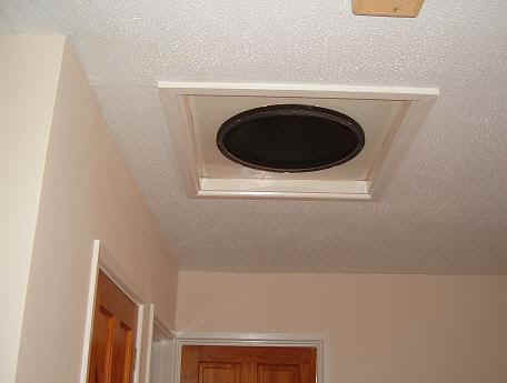
What is the best system - an Infinite Baffle? Having read this far you must have tired of my dismissive criticisms of all the loudspeaker designs discussed. A legitimate question at this point, therefore, is where do we go from here? Until about the 1980's I was still asking myself this question, having spent a lot of time and money in either purchasing, constructing or borrowing examples of all the enclosure designs previously referred to. In spite of various claims none of them proved satisfactory in being able to imitate that subtle sensation perceived in a large building when the soft pedal stops of an organ are used. This situation changed dramatically when I moved into a house that allowed my electronic organ and hi-fi equipment to be installed in a room having its own roof space accessed by a trap in the ceiling. It occurred to me that here was a near-perfect infinite baffle. The ceiling of the room, although made only of plasterboard, was braced at frequent intervals by massive baulks of timber (the ceiling joists). Would that ordinary loudspeaker cabinets were built like this! The large volume of the roof space and the fact that it was acoustically open to the outside world meant that there would be no compressive loading on the rear of the loudspeaker cone, as would have been the case with a sealed box. The fortuitous presence of the access hatch actually in the room itself provided the final temptation to mount a pair of large loudspeakers (300 mm diameter) in the trap door. (Remember that a pair of speakers is four times as effective as one). The arrangement is sketched in Figure 5. The loudspeaker units had a free air resonance of about 35 Hz, and they were mounted along a diagonal of the trap door which was about 25 mm thick.
The results were, to put it mildly, certainly without equal to anything I had previously experienced. Varying the frequency of a sine wave oscillator slowly between 15 and 50 Hz produced the "feel" rather than the sounds of these low frequencies, and at surprisingly low powers. Only 5 watts of electrical power produced results that rattled doors, windows and radiators even in distant rooms, much to the annoyance of my family. The lowest frequencies seemed to permeate the entire house. On the electronic organ itself I had to attenuate the outputs of the pedal stops over the lowest octave to prevent quite deafening results. On the softest 16 foot flue stops I was able to obtain the quiet, breathing bass that had eluded me for so long. In fact, one could hear it rather too well in the garden. To back up all this qualitative stuff I did actually measure the low-frequency response with some care (Figure 6) which confirmed my subjective impressions.
Subsequent to this initial success I was leafing through Beranek's well known book "Acoustics". I was struck by the fact that he wades heroically through the detailed theory of reflex cabinets, horns and the like and, at the end of it all in a hidden little paragraph, mildly suggests that for good bass one should try to create a true infinite baffle preferably using multiple loudspeaker units. The method he suggests is to mount the speakers in the wall of "a closet filled with clothing". Obviously the great Professor Beranek must have had a similar revelation when he tried it! In spite of the jokey images, I am quite seriously suggesting more widespread use of the roof space as a means to achieve an infinite baffle, though obviously I do not claim to have invented the idea. The practical difficulties may not be trivial, particularly if a trap has to be constructed for the purpose. If you contemplate doing this, bear in mind the hazards of modifying the ceiling structure of your house and do not attempt it yourself unless you are sure you know what you are doing. A good position for the loudspeaker is often found to be the existing trap door giving access to the loft in a hallway of the house. There is also a number of other matters to bear in mind. As with all low frequency loudspeaker enclosures, air leakage from points close to the speaker units themselves must be minimised. The board on which you mount the units must be hermetically sealed by seating it on foam rubber draught excluder strip or similar material. Also it is virtually impossible to disguise the ugly appearance of the exposed speaker cones using material such as the ubiquitous loudspeaker fabric. At 16 foot C or below the cones will be executing considerable excursions, and the volume of air moved is therefore considerable also. Interposing any lightweight material at this point leads to unacceptable chuffing and flapping noises in my experience, regardless of how acoustically transparent it is claimed to be. Circular metal grilles can be obtained which should not exhibit this problem, provided their holes are of substantial size so they do not impede the air flow. However, whether they improve the aesthetics of the installation is an open question. You must also protect the speaker cones (if of paper) from the attentions of mice. In the past I have surrounded the units with tubes of corrugated cardboard topped by plastic garden mesh. This will not stop these pesky rodents but it will slow down their predations. (By far the best method is to send a cat into the roof space occasionally. Being so curious, cats are usually keen to cooperate, and this technique works like magic in keeping your roof vermin-free). You will also need to prevent condensation within the roof cavity dripping onto the cones during cold weather, and in cases where this occurred I have made covers for the rear of the loudspeakers from the boxes in which they were shipped. Plenty of large holes to allow air to be pumped in and out of the sides of the cover as the cone moves must be included, however. The ceiling loudspeaker system can of course be used for wide range reproduction from a suitable unit, but if more than one unit is used it is advisable to restrict operation to low frequencies only. Multiple loudspeakers will produce interference peaks and nulls in the response at medium frequencies and above, and in my case no frequencies above about 170 Hz are fed to the ceiling loudspeakers. A number of similarly successful installations of this type have been made, both by myself and on my recommendation. All of them are used for 32 foot as well as 16 foot reproduction. At the time of writing, the most recent was installed in 2003 in the loft hatch of the stairwell in an ordinary two storey house. It uses a single 450 mm (18 inch) Omega Pro 18 loudspeaker unit by Eminence, driven by a modest 60 watt amplifier. This one causes much rattling of adjacent doors on certain notes in the 32 foot octave but, as the owner rightly observes, it demonstrates the amount of power that is being radiated, and he regards it as no more objectionable than the similar effects which occur in a cathedral! He reduces the rattling problem by simply opening all of the doors before commencing to play. Currently I use a similar system myself (Figure 7).
Figure 7. My current installation using an Eminence 18 inch Omega Pro loudspeaker The effectiveness of the ceiling as a loudspeaker baffle depends on the rigidity of its construction, and all of the foregoing relates to the form of construction for suspended ceilings in modern domestic buildings which comply with the Building Regulations in the UK. These lay down minimum dimensions for ceiling joists, their maximum allowable separations and other parameters such as the maximum permitted span without intermediate supports. It happens that suspended ceilings constructed in this way are well rigid enough to satisfy the acoustic requirements of a low frequency baffle, as the measurements in Figure 6 show. However if the ceiling you are intending to use is not constructed in this manner it is possible the results may not be as satisfactory. In these circumstances, another method of creating a suitable baffle is to mount the speakers in a wall separating one room from another. Commonly such walls will be studwork partitions, thereby reducing the labour involved, and while acoustically less attractive than a solid wall of brick or blocks, they would probably be at least as effective as the ceiling mounted system. Alternatively doors or cupboards/closets could even be tried, as Beranek suggested. While at first sight these techniques may sound crazy, it has been the object of this article to show that nature demands extreme methods for the reproduction of extreme bass. The methods described seem no more outrageous than (for example) the folded concrete horns employed by other of the cognoscenti! Anyone who claims that the same results can be obtained from acoustically small structures must also reflect on why 32 foot organ pipes have to be 32 feet long.
The Effect of the Listening Room The excitation of standing waves caused by reflections in the listening room is a well known phenomenon. If a loudspeaker emits a sound in the room, that sound will be heard together with its reflections at all of the surfaces. What enters your ear is the continuous and instantaneous arithmetical sum of the air pressures of all these waveforms. At some instants the summation process augments the sound level of the waveform compared to its original value, whereas at others it reduces them. These effects will vary depending on listening position within the volume of the room. A standing wave exists at a particular frequency when the signal phases of a few particularly dominant reflections conspire to augment or reduce the radiated sound, and these exist mainly at low audio frequencies because at higher frequencies there are so many room modes that individual standing waves at specific frequencies tend to be obscured. In an ordinary room a standing wave will be set up between two parallel walls (not containing large windows or apertures) at a frequency corresponding to a wall separation of half a wavelength, assuming that a sustained tone having this frequency is being radiated by a loudspeaker. This is a form of resonance. In a medium sized room with one dimension around 5 m (half a wavelength at 32 Hz or 16 foot C) a pronounced resonance at this frequency is often subjectively obvious. At first sight this is great, because at least you will hear notes at pitches corresponding to the room resonances. Unfortunately, there are not many resonances at such low frequencies in small rooms so the reproduction of pedal notes will suffer from several deep peaks and troughs. Also, for a room to resonate at 16 Hz corresponding to the bottom note of a 32 foot stop, there are even fewer resonances. Worse still, half a wavelength at this frequency is about 10 m, which implies a room of substantial size. Therefore if you are fortunate enough to have such a room in your house it should be used for purposes involving the reproduction of 16 or 32 foot pedal tones - if the other sorely-tried members of your household agree. Incidentally, if you convert these room dimensions to Imperial units you find they approximate to 16 feet (for a 16 foot stop) and 32 feet (for a 32 foot one). Surprise, surprise! This is because open flue pipes are always about half a wavelength long. What happens if you do not have such a room? Conventional wisdom teaches that it is not a problem because small rooms can be better than large ones for low frequency reproduction due to a phenomenon called 'room gain'. As a room gets smaller, its volume becomes a larger fraction of the volume of air moved by the loudspeaker cone. Thus the loudspeaker begins to actually pressurise the air in the room as its cone moves outwards, and the opposite (rarefaction) occurs when it moves inwards. This is why many pundits declare that low frequency reproduction in cars is so good. Aside from the nonsense that no sensible person would seriously propose a car as the reference enclosure for serious high fidelity listening to organ music, the claim is entirely illusory for other reasons. This is because real rooms of whatever size are leaky, thus in practice the pressurising argument collapses before it begins. In fact, room gain in real rooms applies more to medium and high frequencies rather than to low ones, but the explanation is entirely different. It has nothing to do with pressuring effects but depends instead on resonances or room modes due to standing waves. As the frequency goes higher, the number of modes also increases until there is some resonance at or close to virtually any frequency. This veritable forest of closely-spaced resonance peaks in the upper reaches of the room frequency response enhances the power available for listening at higher frequencies, because it is not lost beyond the room boundaries. Thus it is indeed valid to call it room gain. But other room effects also intrude at low frequencies, one of which is that the reflections which occur at the boundaries can result in cancellation, not enhancement, of the sound within them. This is because some of the reflections result in a phase change, leading to phase cancellation within the room. This type of reflection occurs at apertures such as doors and windows. Even if phase cancellation does not occur, the fact that acoustically small rooms do not support low frequency standing waves means there is no room gain at these frequencies as there is at the higher ones. Therefore low frequency sounds are perceived to have a lower volume than higher ones, where a huge number of standing waves can exist. This does not mean that you will hear absolutely nothing. The situation is quirky for many reasons, and there will sometimes be places in the room where you can hear low frequency sounds well at particular frequencies. But both the positions and the frequencies will be critical, thus such rooms can scarcely be considered to be practical listening environments for extreme bass. The low frequency sounds which you do hear in small rooms are also spectrally distorted because the room generally will resonate at the higher harmonics which have smaller wavelengths, and therefore these will be artificially emphasised with respect to the fundamental at which no resonances occur. This is another effect of the frequency-dependent room gain mentioned above. The issues above relating to real rooms are expanded in reference [1].
So why can we hear bass notes so well in good quality headphones? Here, the dimensions involved are tiny compared to even the smallest room and the average loudspeaker. Yet I have just emphasised how important it is that these dimensions should be maximised! Even with the tiny inexpensive earpieces which come with portable music players the bass is astonishingly good. The situation here is quite different to that for loudspeakers which radiate into free air. Usually headphones are acoustically open to the air at the rear but they should fit round the ear (or inside it) with a good hermetic seal. Under these conditions the movement of the diaphragm is coupled directly to the ear in the sense that all the pressure variations it induces are transmitted through the ear canal to the ear drum, regardless of frequency. Therefore it is not surprising that low frequencies can be heard. However the bass response is badly affected by ill-fitting earpieces which allow the pressure variations to become equalised by leakage, therefore you should always try headphones on known music material before you purchase them. An incidental property of headphones is of interest. Because the rear of the diaphragm radiates into free air, it acts just like an ordinary loudspeaker and is subject to the same limitations. Because of the tiny size of the radiating aperture, only the highest frequencies with wavelengths comparable to the dimensions of the diaphragm are radiated efficiently. In practice this means only frequencies above a few kilohertz can be heard at an appreciable distance. This is why headphone-wearers are responsible for that annoying tizz-tizz effect which so infuriates other people in public places. You might consider the headphone option for bass reproduction if all else fails. It will work, provided the phones themselves are good enough.
1. The following material has been added to refute some of the arrant nonsense received in various emails since this article was posted, mainly on the subject of room effects. It is astonishing that some of the authors, who claim enough expertise in audio and acoustics to make a living out of it, still think it is adequate to model low frequency room acoustics using the grossest simplifying assumptions. One such modelled a room as a simple sealed box with dimensions negligible compared to the wavelengths involved and then concluded that, as it is pressure driven, it has a flat response down to the lowest frequencies - "like a car" (quote). He clearly has yet to understand the subtleties of organs well enough to realise that you can scarcely adopt a car as the gold standard when listening to them! I wonder what sort of 'music' he prefers when on the move? Another refused to accept that the careful in-room measurements presented in this article were real. Obviously I don't correspond with those who regard me as that mendacious, regardless of who they might be. Although tempted to name these people, they should be relieved I am such a nice guy that I do not wish to embarrass them. The room in which a loudspeaker is situated imposes its own, very pronounced, imprint on the sounds you hear. At low frequencies it is impossible to model these room effects accurately for several reasons. One is that air leakage results in profound changes to the modes which the room supports. For example, a tiny aperture equivalent to 0.25% of the surface area of one wall can result in a 6% change in frequency of the lowest-frequency mode. This, please note, was the result of an experiment, not some idealised theoretical model. Real rooms, of course, are not airtight, therefore this result shows that it is pointless trying to model them as though they are. We do not expect our loudspeaker enclosures to perform properly at low frequencies unless they are airtight, therefore it is laughable when people model leaky rooms as though they are hermetically sealed boxes! If an aperture is not tiny but of significant size, such as an open door or a stairwell, considerable acoustic energy will leak from the room. This means the normally high acoustic impedance of a hard wall without an aperture becomes much lower. Moreover the impedance value is frequency dependent, almost always becoming lower as the frequency gets lower. In simple terms this means that the acoustic vibrational pressure at the aperture becomes progressively smaller at low frequencies, which is not surprising when we realise that the pressure obviously dissipates through the aperture as energy propagates into the environment beyond the room. Pressure cannot remain high when there is nothing to constrain molecular vibration. OK, so shut the doors, you might retort. However a closed door is still not airtight, and you cannot easily close off a stairwell. Nor can you do much about windows. If they are large relative to the wall in which they are inserted, windows can also behave as though they are apertures open to the outside world. If you can hear low frequency sounds coming into the room from outside, and you usually can, this means the acoustic impedance of your windows is low at these frequencies. Organ builders know that large windows in a building leak the bass notes dramatically - the sound literally goes out of the window, leaving the organ sounding scratchy and unpleasant in some cases. This effect also explains why, as you approach a church, you hear only the lowest pedal notes at first because it is these which preferentially leak out of the building through the windows into the churchyard. These impedance modifiers (doors, windows and other apertures) mean that sound reflected from the surfaces containing them is changed in phase. This is because a leaky boundary has an end-effect similar to that in organ pipes where the pressure node at which reflection effectively takes place lies beyond the boundary itself. This contrasts with the usual unrealistic assumption made when modelling modes in rooms that there is no phase change at any of the internal surfaces. The phase changes result in a standing wave (mode) pattern at low frequencies which can differ wildly from that predicted by elementary modelling approaches. In turn, the standing waves actually obtained, as opposed to those predicted by simple theory, dominate the way a real room responds to the lowest frequencies. In some cases a particular mode might not exist at all. This can occur in the same way that some modes in wind instruments are suppressed by a combination of a high impedance at one point with a low impedance at another. A real room exhibits a multiplicity of such effects with its combination of hard walls (high impedance) and apertures (low impedance). Similar mode-suppression effects occur when small holes are drilled deliberately in the walls of organ pipes (which confirms the sensitivity of standing wave formation to the smallest apertures, as noted above). Phase changes occurring at some boundaries but not at others also result in acoustic power distribution patterns which are unsymmetrical relative to the room. This contributes to the general quirkiness and unpredictability of low frequency perception in small rooms which everyday experience confirms. Another factor which must be taken into account is that the lowest-frequency modes in real rooms, even the axial (wall-to-wall) ones, are often anharmonic, that is, they occur at frequencies which are not integer multiples of the lowest. This is an inescapable consequence of the variation of phase change with frequency which occurs on reflection at the boundaries of real rooms. All these effects modify the spatial distribution of acoustic energy within a room at all frequencies, not just those at which standing waves occur. Because it is impossible to model them accurately, it follows that it is impossible to predict how low frequencies will be perceived as one moves around within the volume of the room. Nor should it evoke surprise that low frequency perception is so capricious and difficult to comprehend.
|