


|
|
|
Swell boxes and swell pedals - Part 2: Mechanisms
Colin Pykett
"Methods of swell-shutter control are legion but few are satisfactory" W L Sumner
Posted: 17 December 2023 Revised: 22 December 2023 Copyright © C E Pykett
Abstract. A previous article [1] discussed the acoustic effects of swell boxes on the sounds of the enclosed organ pipes, and this sequel now looks at the wide variety of mechanisms which have been used to operate the swell shutters. In a single web page it would be impossible to include every known system so, instead, a broadly historical approach has been adopted to show how the main types of mechanism arose from the enabling technology which evolved across engineering more generally as time went on. Beginning with both unbalanced and balanced mechanical linkages between swell pedal and shutters, it is then shown how the need for remote control became pressing in the nineteenth century when pneumatic and electric actions made possible distantly-detached and sometimes mobile consoles. The influence of Robert Hope-Jones is necessarily discussed, who incorporated a novel electric servo mechanism in his first organ at St John's, Birkenhead, and who soon afterwards applied individual electropneumatic actions to each shutter in later instruments. To control the latter he introduced the multi-stage switch operated by the swell pedal which remains in use to this day.
Other techniques including the whiffle tree and Willis's 'infinite speed and gradation' system are discussed, and the article closes with some remarks about current and likely future trends in swell shutter control. However, despite the plethora of remote control techniques which have been tried, not all of them have enabled the immediacy and sensitivity of the continuously variable control offered by a well-engineered mechanical swell action to be achieved, and unfortunately this shortcoming remains far from unusual today.
Contents (click on the headings below to access the desired section)
The influence of Robert Hope-Jones:
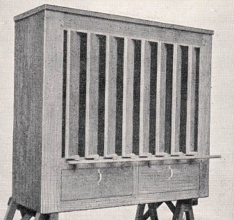
Figure 1. A swell box with open vertical shutters
Made by J J Walker and illustrated in Sir Walter Alcock's tutor 'The Organ' in 1913
A previous article [1] discussed the acoustic effects of swell boxes on the sounds of the enclosed organ pipes - a typical box with vertical shutters in the 'open' position is illustrated in Figure 1. This sequel now considers the wide variety of mechanisms which have been used to operate the shutters, but since this is a subject which could easily fill a book of its own, no attempt is made to include every known system on this single web page. Instead, a broadly historical approach has been adopted to show how the main types of mechanism arose from the enabling technology which evolved across engineering more generally as time went on. Thus, and as in part 1, we will start at the beginning with Abraham Jordan's design installed in the organ of St Magnus the Martyr in London in 1712.
Jordan's swell box had a single large sliding shutter similar to a sash window controlled by a foot-operated lever, but numerous variations have followed since. One of the more important was the replacement of the single shutter by a number of smaller ones, each pivoted separately and arranged either horizontally or vertically in the manner of a Venetian blind, as in Figure 1. However, the use of a lever control is significant as it dominated the type of mechanism used to operate the shutters in British organs until well into the twentieth century and it is still found today. The significance is because the foot can only push down on a lever with considerable force. It cannot easily raise the lever, at least with anything like the same force. Therefore this type of swell box was made to be self-closing so that when the foot leaves the lever, it will attempt to rise again of its own volition unless prevented from doing so in some way. An extant and representative example of this type of lever control is illustrated in Figure 2.
Figure 2. Lever type of swell control
This is in the historic organ of 1858 by J W Walker at the church of St Mary, Ponsbourne in Hertfordshire, England. Note the 'kick stick' with its several ratcheted detents to maintain the shutters in various intermediate positions. (Photo © P R Minchinton)
Thus the lever type of control was unbalanced in the sense that the shutters could not remain in the position they had reached when the foot was removed. In turn, the need to build in deliberate unbalance meant that horizontal shutters had to be employed in which each was pivoted asymmetrically so that it either closed or opened under gravity (usually the former) when the lever was released. Vertical shutters were not common throughout this extended period because they experience no gravitational torque regardless of how they are pivoted. Thus an unbalanced swell box, of which many examples still exist in Britain, usually returns to its closed or minimum volume position when the foot is removed from the control lever, sometimes to the accompaniment of a loud crash if the player is inexperienced. To enable a few intermediate volume levels to be maintained the lever could usually be engaged with notches in a 'kick stick' which was knocked aside by the foot when necessary. This can be seen in Figure 2. It is therefore difficult to imagine a less convenient and cruder piece of mechanism than this form of control which dominated the enclosed divisions of British organs for some two centuries. The disadvantages were amplified when the lever projected at an awkward angle from the extreme right hand side of the console, requiring the player to adopt a posture not unlike that of a dog engaging with a lamp post. Many musical instruments have their idiosyncrasies but they should not be allowed to become ridiculous, and it therefore surprises me that the unbalanced lever type of swell persisted for so long. But, having expressed an opinion, arguments for and against the unbalanced and balanced configurations were aired frequently in the musical press in the Victorian and Edwardian eras, and they still surface occasionally today.
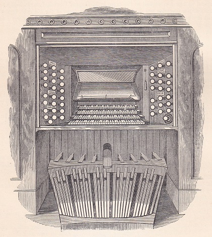
Nevertheless, on the basis that it is now made almost exclusively, it is fair to say that a balanced swell mechanism is more ergonomically attractive to most organists today since its control pedal, and therefore the shutters, will remain in any position. For this reason the shutters in this case are usually mounted vertically so that there will be no gravitational torque acting on the pedal linkage. At the same time the pedal is usually exactly that, a hinged or pivoted pedal rather than a projecting lever, placed towards the centre of the console and just above the pedal board so that it can be operated by toe or heel pressure from either foot [2]. It is baffling why it took so long for this balanced form of swell control to gain the ascendancy, at least in Britain. However, despite the slow progress, an engraving from an Edwardian publication [6] is reproduced here at Figure 3 to demonstrate that balanced swell pedals were already in common use - there is no hint in the accompanying text suggesting that the system was regarded as in any way novel or exceptional by that time.
Figure 3. Edwardian engraving of a console with a balanced swell pedal c. 1910
Details of the swell action, the internal mechanics linking the control lever or pedal to the shutters, will not be discussed other than to remark that diverse assemblies of wooden or metal rods (called 'traces' in organ building parlance) or rotating shaftwork ('trundles') were, and still are, employed [3]. Similar to beefed-up versions of the trackers, stickers and rollers used in a mechanical key action, these components obviously have to be configured to suit the unique internal layout of each organ. However, with the arrival of pneumatic and electric actions in the nineteenth century, and particularly those with the distantly-detached and sometimes moveable consoles facilitated by these innovations, a purely mechanical connection became no longer feasible in an increasing number of cases. This resulted in the appearance of a bewildering variety of remote control mechanisms, the more important of which will be described presently. However it is well to bear in mind that not all of them enabled the immediacy and sensitivity of the continuously variable control obtainable from a well-engineered mechanical swell action to be achieved, and unfortunately this shortcoming remains far from unusual today.
The influence of Robert Hope-Jones
Robert Hope-Jones MIEE (1859-1914) was the controversial yet profoundly influential British electrical engineer and organ builder who laid the foundations of the electric actions used subsequently across the world. As in all other aspects of electrical control of the organ, he invented and patented prolifically in the remote management of swell shutters throughout his working life both in Britain and subsequently in the United States. This was a natural outcome of his being the first to apply a systems engineering approach to the design and realisation of electric actions. Earlier attempts had focused mainly on the key action alone but, although taken for granted today, his wider vision embraced the electrical control of a total system comprising not only the key action but the speaking stops, couplers and combination mechanism as well as the swell shutters themselves.
From the outset Hope-Jones invented and used several types of electropneumatic servo mechanism for controlling swell shutters. I have described his work in detail elsewhere [4] so the following material merely summarises the main features of his thinking. The first application of his ideas was to his famous prototype instrument of c. 1890 at St John's church, Birkenhead [5]. This organ had a small, detached and moveable console connected by a multi-core cable long enough to enable the instrument to be played from outside the church porch if need be, so a mechanical swell pedal connection obviously could not have been used.
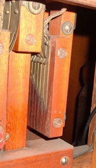
Figure 4. Electric servo mechanism used by Hope-Jones at St John's, Birkenhead c. 1890
Referring to Figure 4, the swell shutters (not shown) are balanced and ganged together mechanically in the usual way (e.g. as in Figure 1) and controlled electropneumatically by two large (and therefore powerful) bellows-type pneumatic motors, one to close and one to open them. Thus if the control magnet of one motor assembly were to be energised, the motor will inflate (or deflate, depending on how the action is designed) and continue moving either until the current is removed or until the shutters can move no further. If the other magnet is energised the same thing will happen but the shutters will move in the opposite direction. The swell pedal and the shutter linkage each operate their own variable resistor, each of which is connected to a separate winding on a specially-designed comparator relay. When the currents flowing through both windings are equal a moving contact sits between a pair of fixed ones and no circuit is made, but if there is a significant imbalance in the currents, the moving contact closes one circuit or the other and thereby inflates (or deflates) one of the large shutter motors. Therefore a movement of the swell pedal alters the current flowing through the corresponding coil of the relay, and this causes the shutters to move until the current is equalised in the other coil.
It might be thought that this system provided precise control of shutter position which was related to the continuously variable analogue control current supplied by the swell pedal resistor in the distant console. Although approximately true, in practice this would not have quite been the case. In servo engineering parlance this was a bang-bang rather than a proportional control system such as the brake servo in a car, meaning that it could only switch between two states in a similar way to the thermostat in a heating system which is either fully on or fully off. Bang-bang servos therefore move abruptly between the two states, but with a hysteresis effect which causes a discontinuity between the input demand and the output response. In this case hysteresis would have been manifested by the shutters not responding to movements of the swell pedal smaller than some threshold value, which would have depended on the characteristics of the comparator relay. Thus hysteresis would have required the pedal to move by an amount large enough to get things moving inside the organ - some electropneumatic swell shutter machines still exhibit this effect today. Another potential problem would have been due to the significant inertia of the heavy swell shutters which might have caused overshoot and a consequential "hunting" problem as the system oscillated briefly around the correct shutter position before coming to rest. Slew rate, the maximum speed at which the shutters can move, would also have been important in this (and any other) type of servo system. But subject to these shortcomings, to which an organist could probably have become accustomed, the system was conceptually simple and it would undoubtedly have worked within these limitations when properly set up and adjusted.
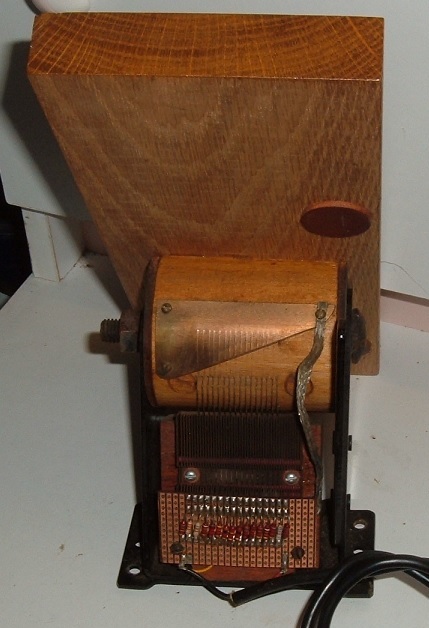
Hope-Jones also developed other methods of swell shutter control which are described in the article referred to already [4]. One of particular interest involved the use of a multi-contact switch in the console which successively and cumulatively closed or opened several circuits depending on the direction in which the swell pedal was moving. One form of this switch, which was fitted to his organ of 1894 at St Paul's, Burton upon Trent, is shown in Figure 5.
Figure 5. St Paul's, Burton upon Trent (Hope-Jones 1894) - swell pedal contacts (Photo © Lancastrian Theatre Organ Trust)
Figure 6. A modern electric action swell pedal by Kimber Allen UK with 16 contacts
One reason why Hope-Jones's multi-contact swell pedal idea has remained in common use for so long is because it is applicable to several different types of swell control. His application of individual actions to each shutter was mentioned above, and another quite different though still compatible mechanism is the whiffle tree. The clever animal-harnessing device of a whiffle tree has been used for centuries to distribute equally the load from (for example) a plough across a number of beasts of burden, with Henry Willis in Britain and E M Skinner in America among the first to see that it could be applied to swell shutter control. In an organ the animals are replaced by an array of pneumatic motors which can be addressed individually and cumulatively by a swell pedal of the Hope-Jones style with its multiple contacts. Both tubular pneumatic and electropneumatic versions of the whiffle tree have been used, though the latter are now universal in modern practice.
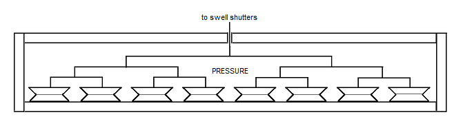
Figure 7. The essentials of a whiffle tree
The essentials of the arrangement are sketched in Figure 7. In this example, eight bellows-type pneumatic motors are connected through levers and pivots to a trace at the top of the diagram which opens or closes the swell shutters. The trace emerges through the top of a box which encloses everything else, the box being charged with wind. The trace moves downwards, pulling the shutters towards their closed position against a restoring spring, when one or more motors collapse. This happens when a valve associated with each motor allows its internal air to exhaust to the atmosphere underneath the bottom board of the box, whereupon the pressurised air in the box squeezes the motor towards flatness. The valve will typically be a disc valve opened by a lever electromagnet when it is energised, each magnet being connected to one of the swell pedal contacts. When the magnet ceases to be energised the trace, pulled upwards by the spring, causes the associated pneumatic motor to rise again and refill with air from inside the box.
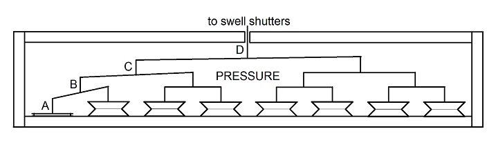
Figure 8. Whiffle tree with one stage activated
A more detailed understanding of how the whiffle tree works can be gained by considering how the lever configuration changes when motors collapse, as sketched in Figure 8. Only one collapsed motor is drawn here, but first imagine the situation if all motors had collapsed. In this case the distance moved by the trace will be the same as the movement of each motor because the entire lever assembly is simply pulled bodily downwards without changing its shape. This is the maximum distance that the trace can move, and let this be denoted by Dmax. Here, the total force acting on the trace is the number of motors multiplied by the force exerted by each one.
The minimum movement of the trace occurs when only one motor has collapsed, as in the diagram. In this case the movement at A is obviously the same as the movement of the collapsed motor. However at B, the movement is only half of this because of the lever action. At C the movement is reduced again to a quarter of that at A, and at D it becomes only one eighth. This is the minimum movement of the trace corresponding to the collapse of only one motor and it therefore equals Dmax/8 as just described. In general, with N motors the minimum movement is Dmax/N. Thus the trace moves in a series of N discrete jumps of size Dmax/N when the swell pedal moves from one extremity to the other. However, although the lever action reduces the movement of the trace compared with the movement of the motor, it also multiplies the force exerted by the motor by the same amount. So in this example the force will be multiplied by eight, or in general by N with N motors, when only one has collapsed. In fact, owing to the two-fold mechanical advantage endowed by each lever when it is pulled away from the horizontal, the force exerted on the trace is always the same regardless of how many stages are activated.
Compared to other elements of an organ action, a whiffle tree is a high-energy system (as are other methods of swell shutter control) since moving an array of heavy shutters requires considerable force of the order that a player's foot must exert on a mechanical swell linkage. The faster the shutters are required to move, the greater the force required to accelerate and get them moving. This is in addition to overcoming the restoring spring force and frictional forces. Therefore the pneumatic motors have to be relatively large particularly if the wind pressure is low, and the large number of pivots in the system must be well-engineered to handle the forces involved and to reduce lost motion. The system is therefore potentially rather noisy and prone to wear. These problems are magnified when more stages are used, with eight as in the example above being the minimum needed just for relatively crude shutter control. At one church where I played the whiffle tree had become useless only some twenty years after it had been installed - over most of the swell pedal travel there was no shutter movement at all owing to excessive wear at the pivots and other linkages.
"Organists differ in their appreciation of this ingenious system" W L Sumner
Willis's 'infinite speed and gradation' (ISG) shutter control system, introduced in Britain in the 1930s, has remained in a backwater of its own though it is still discussed frequently. The system was different to any other in that the amount the swell pedal was moved forwards or backwards from a spring-loaded central position affected the speed of shutter opening or closure rather than shutter position. Therefore it required organists to develop a new technique for controlling volume effectively. Beyond the patent specification, descriptions of how it worked are rare and therefore misapprehensions are common. The most widespread is that the system offered a continuously variable speed of shutter movement depending on how far the swell pedal was moved from its central position, whereas in fact only five discrete speeds were available for closing the shutters and six for opening them. Thus despite what its name implies and the claims made for it, the system offered coarser speed control than conventional methods.
Beyond some in the organ building fraternity, few today seem to have any idea of how the system worked, although that has not inhibited the widespread airing of opinions. Surviving examples are rare, so I feel fortunate to have formed my own judgements through having played a number of organs fitted with the system. The patent specification explains several essential aspects inadequately or not all. For example, it was necessary to brake the motion of the swell shutters suddenly when the swell pedal returned to its central position, yet the means to achieve this were barely mentioned. There was no explanation of the claim that the swell shutters were accelerated or decelerated automatically when they were near the sensitive fully-closed position. Nor was there any attempt to illustrate the electrical circuitry involved, or the important requirement to provide a visual indication of shutter position at the console, because shutter position was unrelated to pedal position. In reality, the visual indicators originally employed were dashboard fuel gauges as used in 1930s-era cars!
Whether the system worked as intended or how reliable it might have been are questions which are difficult to answer at this remove in time, particularly as so few examples now exist. For instance air leakage would have led to major defects, illustrated by at least two essential features of the mechanism (rapid braking and holding the shutters tightly closed when necessary) depending on the integrity merely of a flimsy leather purse which is subjected to constant flexing. At several points the patent rather overstated its case with claims which are at best not self-consistent and at worst simply untrue. Examples include "a perfect crescendo and diminuendo ... as quickly or slowly as is desired", whereas in fact the speed of shutter movement was limited to just a few discrete values as mentioned above. Moreover one is rendered speechless on learning that "there is no tendency of the operative parts to bind or stick". I suspect most organ builders would be only too delighted to discover how this was achieved!
Technology aside, the ISG system also reflects an interesting episode in the history of organ building from a business model viewpoint, since it illustrates the two-edged-sword nature of intellectual property protection - does one patent an idea or not? Patents allow the patentee unfettered use of an idea free from competition, yet simultaneously they can inhibit widespread customer interest and rapid uptake. Ways round the problem exist, such as the patentee issuing licenses to other firms, but consumer appetite for an invention can seldom be gauged accurately until the patents expire. In the case of ISG it is obvious with hindsight that it was a non-starter from the outset - at patent expiry it simply died [9].
No more needs to be said here since I have written another article on this site which describes the system in detail [7], other than to remark that Sumner's diffident opinion quoted above might have rather understated the reality. My view is that it was little more than a solution looking for a problem, invented at a time when a rising tide of technology was swamping everything else in most fields of engineering - just look at the theatre organ.
Today, it ought not to be beyond the wit of man to implement a fully proportional servo-controlled swell system whose performance is beyond reproach. So it is perhaps curious that at the time of writing (December 2023), electric action swell pedals in manufacturers' catalogues still seem to be variants of the multiple-contact design illustrated in Figure 6 and first introduced by Hope-Jones in the 1890s (Figure 5) [8]. This suggests that the desirable goal of smooth, continuously variable shutter motion of the sort offered by a mechanical connection remains more elusive than the sometimes jerky multi-stage approach that has now been used in one way or another for some 130 years. Sixteen stages are frequently employed today. However rotary electric motors driving a gearbox and crank were introduced some years ago to move the shutters between the stages instead of the cumbersome devices described in this article, and together with microprocessor control, they can be set up (in some systems) to tailor the sound volume characteristic to suit the organist's taste. For example, if the volume was over-sensitive and difficult to control near to the shutters-closed position, this could be modified by user adjustments to the software parameters which control the motor.
The use of data transmission protocols such as MIDI effectively does away with discrete stages. Since MIDI offers at least 128 stages it can provide smooth and continuously variable control for practical purposes, at least in principle. One difficulty here is the practical one that a rotary potentiometer is often coupled to the swell pedal in a MIDI system and these are notoriously unreliable components having a limited life. However other more reliable options could be used, such as an optical or magnetic rotary encoder at the pedal.
But irrespective of how they are implemented, remote control systems bring their own idiosyncrasies along as inevitable baggage. One concerns slew rate, the maximum speed at which the shutters could respond if the swell pedal were to be moved quickly from one extreme to the other. However this can be a somewhat contrived criticism, since the slew rate of even a mechanical connection is limited by the maximum force that the player can exert. So while the issue therefore has to be tempered by realism, it does not provide an excuse for control systems with slew rates that are patently too slow. But efforts to increase slew rate have led to consequential problems such as reductions in service life due to gear-stripping or premature bearing failure in motor driven systems. Such difficulties arise because any swell shutter control mechanism involves exerting substantial forces on heavy assemblies having high inertia, thus trying to make the shutters move faster can become a major engineering challenge. The organ building world is deliberately conservative because its products are extremely expensive and customers quite reasonably expect them to last for a long time, far longer than commodity products such as cars or consumer electronics. Therefore perhaps it is no surprise that the tried and tested multi-stage approach has survived for so long, even though it appears today in modern guises.
I am grateful to my friend, Mr Paul Minchinton, for many helpful discussions and particularly for the photograph of the lever control at St Mary's, Ponsbourne which is included here at Figure 2 above.
1.
"Swell boxes and swell pedals - Part 1:
Their effect on organ pipe sounds", an article on this website, C E Pykett 2023.
(See the "swell shutter actions" section).
|