


|
|
|
A Switching Delay Unit for Loudspeakers
Colin Pykett
Posted: 2 February 2021 Revised: 2 February 2021 Copyright © C E Pykett
The articles for DIY enthusiasts on this site relating to virtual pipe organs attract a lot of interest, so here is another. (They also attract a lot of interest from the trade as well!). It describes a unit which inserts a short delay between switching on the mains supply to a digital organ and connecting the loudspeakers to
the amplifiers. This prevents the unpleasant noises which occur otherwise, and it also prevents damage to the loudspeakers themselves. It also disconnects the speakers before removing the power to the amplifiers when switching the organ off. An attractive feature is the push button switch plate used at the console, which has the look and feel of a typical pipe organ starter. When a lot of effort has been put into a digital simulation these small additional features can make all the difference to the satisfaction the instrument provides.
Contents (click on the desired section)
Switching Additional Loudspeakers
WARNING - This circuit is connected to, and controls, the AC mains supply to the amplifiers in a digital organ and (if desired) the organ itself. Therefore some parts of it are "live" or "hot" (they operate at mains voltages). The circuit should not be built nor operated unless fully enclosed in a plastic case as described. Do not connect it to the mains with the lid of the case removed. Do not touch any part of the circuit unless the power cord is unplugged from the mains socket. The circuit must not be used unless connected to a 3 pin mains socket with a properly functioning earth (ground) pin. For added safety the mains supply must incorporate a RCD (residual current device).
This is not a project for the inexperienced constructor. Do not attempt to build it unless you know what you are doing, are familiar with mains wiring practices and construction techniques, and are able to test it for safety. The article is offered in good faith but you proceed entirely at your own risk.
With high quality, high power loudspeakers it is desirable to connect them to the amplifier outputs a short time after the amplifier itself has been switched on, and similarly to disconnect them a short time before the mains supply to the amplifier is switched off. This prevents the unpleasant thuds, pops, cracks, bangs and other noises which occur otherwise, and it also prevents damage to the loudspeakers themselves. Without such precautions, one only has to observe the speaker cones when switching amplifiers on and off to observe what violence they are subjected to. Typically the cones will move far beyond their safe excursion limits. Even in cases where there is little or no audible effect, the cones will often be pushed slowly in or out by a large amount at switch-on or switch-off. This undoubtedly contributes to some cases of premature failure of loudspeaker units, in which the voice coil is found to be mechanically detached, electrically disconnected or burned out. DC-coupled power amplifiers which use both positive and negative power supplies symmetrical about zero can still expose loudspeakers to these problems, even though they do not usually use a large electrolytic capacitor in series with the speaker. In AC-coupled amplifiers using a single (non-symmetrical) power supply, such a capacitor is always used and it charges and discharges through the voice coil and produces the undesirable effects. However a DC-coupled amplifier can still produce similar effects either because the two halves of its power supply rise or decay at different rates, or because the low level signals applied to the amplifier inputs arise from circuitry using a single power supply. In the latter case the charge or discharge of the inevitable coupling capacitor at the input appears at the output as the large transient signal we are speaking of. Capacitors always introduce switch-on and switch-off transients in the loudspeakers regardless of whether they are at the input or the output of an amplifier, or anywhere else in the signal path. With digital organs, the noises themselves are ugly and they immediately reveal that the instrument is electronic and that the makers could not be bothered to do anything about it. The noises can be particularly bad if external reverberation units are used to process the signals applied to the amplifiers since the sounds thrash around audibly for several seconds until they settle down. The design in this article protects the loudspeakers from transients both at switch-on and switch-off and I have applied it to several electronic organs. However, be aware that it does not disconnect the loudspeakers in the event of catastrophic failure of an amplifier which results in DC being applied to the speaker. Before attempting to build it, also be aware that it switches mains voltages which can be lethal if not handled properly. Therefore you should not undertake its construction unless you are fully conversant with the safety issues involved and have the necessary experience with electronics. You proceed with what follows entirely at your own risk.
1. Number of loudspeaker channels: 4 (can be increased to any number). 2. Switch-on delay between applying mains power to the amplifiers and connecting the loudspeakers: typically 4 seconds. 3. Switch-off delay between disconnecting the loudspeakers and removing mains power from the amplifiers: typically 200 msec.
4. Maximum switched mains current (with the mains relay suggested later): 10 A.
5. Maximum switched loudspeaker current (with the speaker relay suggested later): 7 A per channel.
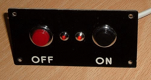
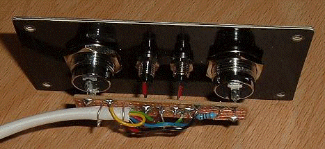
The system is controlled from the console using two push buttons as illustrated in Figures 1 and 2, which show two examples I have made for different organs. In both cases, one button switches the amplifiers (and the whole organ) on, and the other switches them off. I chose this scheme deliberately to imitate the style of a typical push-button starter of a pipe organ blower. In my view it gives a rather satisfying finishing touch to the console of a pipeless organ. The simulated “starter plate” shown in Figure 1 was made from Traffolyte (or Traffolite), a generic name for the laminated phenolic sheet material widely used since the1920’s for engraved labels.
Figure 1. A typical console switch plate
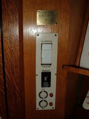
In Figure 2 the plate was made from grained Ivorine as used for stop tabs and key coverings, and it contained several other controls for the instrument concerned besides the on and off buttons.
Figure 2. Another example of a console switch plate
Two small lamps or LEDs are also used and they can be seen in both pictures. One indicates that the organ is connected to a mains supply (standby mode) and ready to be switched on, and the second indicates when the loudspeakers have been connected so that the organ is ready to be played. This happens about 4 seconds after you have pressed the “on” button. The standby LED illuminates as long as the organ remains plugged into a live wall outlet, thus it nags you to disconnect it physically when you have finished playing. However, like many other appliances, it is your choice whether to do this, and if you do not disconnect it then the standby LED will remain lit all the time. This practice is to be deprecated on safety grounds for any item of electrical equipment in my opinion.
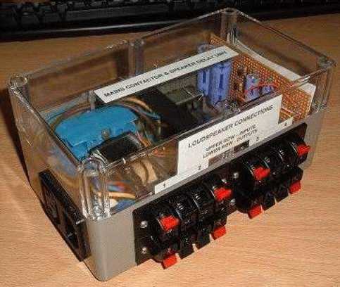
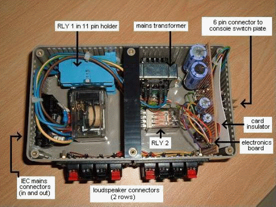
The starter plate with its push buttons and LEDs is connected via a small 6-core cable to the electronics unit, shown in Figure 3. Because the electronics unit switches mains voltages as well as the loudspeaker signals, it consists of a fully insulated plastic box whose lid can only be removed by physically removing six recessed screws. This prevents accidental exposure of mains conductors. However only low voltages, around ±12 volts DC, are present at the starter plate itself.
Figure 3. Electronics and relay module of the system
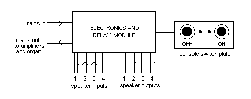
The system is connected as in the general arrangement shown at Figure 4, where the box labelled “electronics and relay module” corresponds to the picture shown above (Figure 3). This unit is interposed in series with the mains inlet lead instead of connecting it directly to the organ, thus it switches the mains supply to the organ and therefore to the amplifiers as well. The loudspeaker feeds from the power amplifiers (four in the diagram) are first taken to the unit, which therefore switches the audio signals to the loudspeakers after the proper time delays. A further cable connection is taken from the unit to the console plate containing the push buttons and LEDs.
Figure 4. General arrangement of the system
The circuit of the unit breaks down into two main sections – a power supply, and the relay control circuitry. Both sections are contained in the insulated plastic box for safety reasons. An annotated picture of the internal layout of my prototype box showing the main components is at Figure 5.
Figure 5. The main components of the system
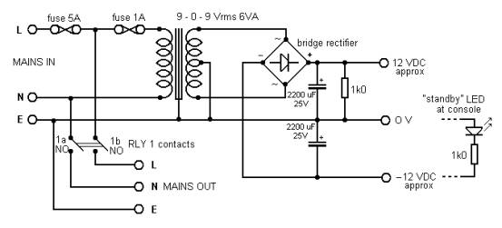
The power supply circuit schematic is at Figure 6, and it goes without saying that the greatest care must be exercised when assembling this in view of the mains voltages which are switched at this point. The mains supply enters the unit via the 5A fuse in the live lead. You must confirm that this rating will be appropriate for your organ, and if not then change it. In the UK this fuse can conveniently be the one incorporated in the plug top which plugs into the wall outlet, which then makes it unnecessary to put an additional fuse inside the unit itself. Bear in mind that the relay recommended later on which switches the mains supply to the organ has a maximum current rating of 10A.
In this and subsequent diagrams relating to the relay contacts the symbol 'NO' means 'normally open' and 'NC' means 'normally closed'.
Figure 6. Power supply circuit
The mains input and output to the unit were taken in and out via IEC 3 pole mains chassis connectors in my system. Ensure you use the correct gender (male or female) for the input and the output connectors so that mains voltage cannot appear on exposed pins which could be touched. Also note that the wiring sense of the live and neutral pins of the two genders is different, and therefore you should look carefully for the L/N/E legends which should be visible on the connectors themselves. Often, these connectors require the use of push-on crimped terminals. In such cases I prefer to solder the wires into the crimp terminals instead of (or as well as) crimping them. Also, for safety’s sake should the lid of the box be removed, put insulated sleeves over these terminals. The mains supply going out to the organ is double switched in both the live and neutral lines by two normally-open contacts (1a NO and 1b NO) of relay 1. This is a 10A 3 pole changeover (3PDT) component with a 12VDC coil which plugs into a standard 11 pin relay holder. Two of the poles are used to switch the mains supply as just mentioned while the third pole (1c) is used by the control circuitry, described presently. This is an industry standard power relay widely obtainable from many sources and one source of supply is suggested later. The pinout of the 11 pin relay holder can be confusing, and for safety reasons it is obviously vital to spend time ensuring that you have got this aspect of the assembly correct. The pinning arrangement is in the table below. All 11 pins of these relays have a function and are connected internally, but only those actually used by this circuit are mentioned in the table :
It is strongly suggested you test the connections to ensure you have them correct before applying mains voltage. Wire the holder as shown in the table and have a source of 12 VDC available to temporarily energise the relay coil during testing. Use an ohmmeter or low voltage continuity tester to check that the following conditions apply:
With no voltage applied to the coil the following pairs of pins should be open circuit :
1. 1 and 3 2. 6 and 7 3. 9 and 11
With 12 VDC applied to the coil (pins 2 and 10) all the above pairs should now show a short circuit. In addition, while keeping the relay energised, check there is no continuity between any of the other pairs (i.e. between 1 and 6, 6 and 9, and 1 and 9).
Having done this it is desirable not to disconnect the wiring again to guard against the possibility of mistakes occurring when rewiring the holder subsequently. Therefore when hooking up the holder for the above tests, use overlength wires of the correct gauges and colours and then trim them to length when finally wiring the holder into the rest of the circuit. In the UK the correct colours for mains conductors are brown for live, blue for neutral and green/yellow stripes for earth (ground). To avoid confusion do not use these colours for the other non-mains connections to the relay holder.
Returning to Figure 6 a second fuse, rated at 1A, feeds a small transformer with a centre-tapped secondary providing 9 - 0 - 9 VAC rms from which unregulated DC supplies at about ±12 volts are derived. The transformer suggested later also has a centre-tapped primary, which means it can be configured either for 110 or 220 VAC mains supplies.
I used four 1N4002 diodes as a bridge rectifier. The lamination stack of the transformer is deliberately earthed (grounded) as shown in Figure 6 in view of the use of a plastic case. This can be done by using a solder tag under one of the mounting nuts or bolts. The zero volts line of the power supply is also earthed. A 6 VA transformer will suffice unless a large number of loudspeakers are to be switched, in which case multiple loudspeaker relays will also be needed as described later. The unit described here will switch up to 4 loudspeakers using a single 4 pole relay (RLY 2), using the circuit described presently.
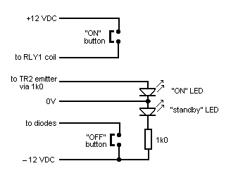
The “standby” LED at the console is fed from the negative supply, and it also serves to discharge the electrolytic smoothing capacitor when the mains supply is removed. A separate 1k resistor is fitted across the positive supply to perform the same function. This bleed resistor is important, as omitting it can result in some strange behaviour when the unit is disconnected from the mains.
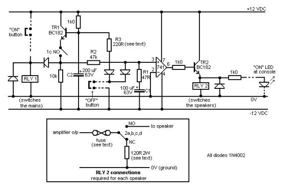
This is shown in Figure 7. Unlike the power supply circuit discussed in the previous section, everything here operates at low voltages although this does not reduce the need for care if you want a system that will actually work properly.
Figure 7. Relay control circuit
The way the system works is as follows:
When the mains is connected to the system, only the “standby” LED illuminates at the console, and in addition ±12 VDC is supplied to the circuit. When the “on” button is pressed, it applies 12 VDC to the coil of RLY 1 which therefore pulls in immediately and switches the organ and its amplifiers on via contacts 1a and 1b (see Figure 6). The change of state of the relay also closes its third contact 1c, which thus maintains the supply to its coil via transistor TR1 after the “on” button has been released. The closure of contact 1c also begins to charge C1 via R1 and R2. When the voltage across C1 reaches zero volts, it causes the 741 operational amplifier (configured as a voltage comparator) to change state rapidly. The pin numbers of the 741 in the diagram are those of an 8 pin DIL (dual-in-line) device. The change of state at pin 6 is from around -12 volts to +12 volts, and it therefore energises relay RLY 2 via transistor TR2. In turn this connects all the loudspeakers to their respective amplifiers after the unpleasant switching transients have died away. With the component values shown this delay is a few seconds. The use of a relay completely isolates the loudspeakers from each other and from any of the circuitry of the delayed switching system.
When the “off” button is pressed both C1 and C2 are discharged quickly, typically in a few hundred milliseconds. The component values shown in the diagram result in RLY 2 (which switches the loudspeakers) dropping out slightly before RLY 1 (which switches the mains supply to the organ and amplifiers). Therefore the speakers are disconnected just before the amplifiers are switched off, thereby again preventing unpleasant noises and possible damage. The sequence in which the two relays drop out is of course a desirable requirement, but in view of the wide tolerances of the electrolytic capacitors used for C1 and C2 it is possible RLY 2 (the speaker relay) will not drop out before RLY 1 (the mains relay). If this is the case, reduce the value of R3 or, in extreme cases, C2. However this is unlikely – I have built several versions of this circuit and have yet to meet this problem. Neither R1 nor R3 should be omitted, otherwise large transient currents will flow through the "off" button. This could damage both the button itself or the associated capacitors over time.
The loudspeaker connections to RLY 2 are shown in detail in the lower box in Figure 7. It is important that each loudspeaker remains isolated from all the others, and from the rest of the circuitry of the system. Therefore the line marked "0v (ground)" in this box in Figure 7 refers solely to the 0v line of the amplifier feeding each loudspeaker. It is not connected to any other speaker supply line, nor to the line labelled "0v" of the relay control circuit above. Otherwise this could cause instability with some amplifiers, or mains hum due to the introduction of hum loops. So ensure your wiring does not inadvertently connect the ground lines of your amplifiers in parallel. With the relay suggested (see later), up to four loudspeakers can be controlled. A fuse is shown in series with each speaker feed but this can be omitted if fuses are already incorporated in the amplifiers. A 120 ohm resistor is also shown which is connected across the output of each amplifier while the speakers are not connected. This resistor is only required if the amplifier has a large electrolytic capacitor in series with the corresponding loudspeaker. Therefore until the loudspeaker is connected via RLY 2, the capacitor charges via the resistor. Otherwise you will still get some sort of noise and possible damage when the speakers are finally connected, even when using this delayed switching unit. This will negate any value you would otherwise have expected.
If this situation does not apply in your case, i.e. if you are using DC coupled power amplifiers which do not have output capacitors, the 120 ohm resistors can be omitted.
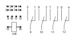
A number of points have been made already about the constructional details of this unit. Figures 3 and 5 are views of the outside and inside of the plastic box containing all the components apart from the console push button plate. Mains connections use IEC chassis connectors as already described. The loudspeaker leads are terminated using standard stereo pairs of sprung speaker connectors arranged in two rows – the upper row is for the inputs from the four amplifiers and the lower for the corresponding outputs to the four loudspeakers. As mentioned already, each pair of wires to each loudspeaker is isolated from all the others – the ground leads are not connected together for example. Nor are any of the speaker leads connected electrically to the control circuitry inside the box, not even to the mains ground. Thus the speaker inputs and outputs are connected only to their respective contacts on RLY 2, which isolates them from each other and from the other circuitry inside the box as mentioned above. This relay is a 4PDT device with a 12V coil and it will handle up to 7A through each contact, which means nearly 400 W continuous power can be supplied to an 8 ohm speaker. It can be used with a variety of plug-in bases, but I soldered the speaker leads directly to the pins in view of the high currents likely to be encountered in the speaker circuits. The pinout of the relay is in Figure 8, looking at the pins from the underside. The contacts are shown in their normally closed state i.e. with the relay not energised.
Figure 8. Pinout of RLY2
The two push buttons and two LEDs on the console switch plate require 6 leads to be taken from the box, and I used a substantial 6 pin Jones connector and miniature 6 core intruder alarm cable for this purpose. A DIN plug and socket would probably be cheaper as nothing above ±12 VDC is involved at this point, though it would be flimsier and possibly less reliable. The 6 connections involved are shown in Figure 9. The polarity of connections to LEDs can be confusing but it is vital to get them right, otherwise most LEDs will be destroyed if anything more than about 2 volts is applied in a reverse direction. The positive pole of the supply must be connected to the anode, and with the components suggested later this lead is marked with a '+' symbol. If in doubt, test the LED with a 1.5V dry cell in series with a 1k resistor before wiring it into the circuit.
Figure 9. Connections to the console switch plate
The cable is anchored at the switch plate end by tying it to a small piece of stripboard to which the push buttons and LEDs are also soldered, as shown in Figure 10.
Figure 10. Rear of a typical switch plate showing cable anchoring
The small components used in the main electronics unit are accommodated on a piece of stripboard which can be seen slotted into the box in Figures 3 and 5. A layout diagram is not given here because constructors will be able to concoct their own, or they might prefer to make a proper printed circuit board. Note the piece of card behind the board in Figure 5 – in my prototype this prevented the back of the board touching the connections to the adjacent Jones connector feeding the console switch plate.
It might be useful to list the components used, apart from the small electronic items such as transistors etc which can be obtained anywhere. I got them from Rapid Electronics in the UK (www.rapidonline.com) and the list, including the Rapid order codes, is in the table below:
The plastic case specified is of approximate dimensions (mm) 90 high x 110 wide x 190 long.
Unfortunately it seems to be an immutable law of electronics that whenever you describe a circuit for other people to construct, at least some of the components you used suddenly seem to be magically unavailable. So before publishing this article I checked again today (January 2021) against the Rapid Electronics website and, lo and behold, some of them have been discontinued. However their site helpfully suggested alternatives in these cases.
Switching Additional Loudspeakers The unit as described will switch up to 4 loudspeakers. An unlimited number could be switched in principle, but additional relays similar to RLY 2 would be required. However it would not be possible merely to drive an arbitrary number of relays by putting their coils in parallel with that of RLY2 because the current capacity of the driver transistor (TR2 in Figure 7) might be exceeded. Also the power rating of the mains transformer would need to be increased when driving many relays. One way to solve these problems would be to use a high current Darlington transistor in place of TR2, or to use the existing TR2 to drive an additional higher power junction device in Darlington mode. Then a larger number of relays could be driven in parallel. However it would still be necessary to ensure that the power rating of the transformer was not exceeded. Another way would be to use one of the contacts on RLY2 to switch the additional relay coils, again using an appropriately larger power supply. In this case the existing driver TR2 could be retained. Suppressor diodes would need to be fitted to the additional coils. The additional relays could be remotely sited close to their respective amplifiers since it could become clumsy and inconvenient to have a large number of speaker leads fanning into and out of a single switching unit when more than four loudspeakers were being controlled.
|