


|
|
|
How
the Flue Pipe Speaks
Posted: 18 November 2001 Last revised: 17 December 2009 Copyright © C E Pykett Contents (click on the headings below to select the desired section)
The organ flue pipe and similar wind instruments seem at first sight to be of the simplest structure imaginable. Yet the details of how it works have attracted the interest of musicians, organ builders and scientists for centuries, and it still continues to attract attention today. One reason is the persistence until quite recently of several fundamental misunderstandings, so this article presents a simplified review of the mechanisms involved in pipe speech, tone quality, voicing, scaling and regulation. The actual mechanisms are extremely complex, and in some cases not amenable to detailed analysis at all. This article first appeared in 2001 and it has been a consistent "high-hitter" in terms of the interest it seems to have aroused. Much of it has been used (with and without permission!) in various other publications, presentations, etc. Taking into account some of the correspondence received it was completely revised in 2006, with some new sections added on attack transients and regulation. The article should be easier to read if you allow it to occupy the full screen width on your
monitor, in view of the width of some of the diagrams. The
Basic Mechanism: Generator-Resonator Coupling It is necessary to understand the concept of
generator-resonator coupling in a flue pipe.
The pitch of the pipe is largely controlled by the air in the body of the
pipe, the resonator. The energy
required to set the air in the resonator in motion is supplied by the wind
issuing from the mouth, the generator. Both
the generator and the resonator control the tone quality of the pipe, and they
are closely coupled together while the pipe is sounding. When the pallet of a pipe opens, wind issues as a sheet of
air from the slit-like flue at the base of the mouth and moves towards the upper
lip. In doing so it also enters the
pipe and pushes some of the stationary air aside, and this initiates a pressure
impulse which travels up the column of the pipe at nearly the speed of sound
(about 1100 feet per second or 335 metres per second).
The exact speed depends on factors such as the amount of drag at the pipe
walls. While the impulse is
travelling in the pipe the wind at the mouth also reaches the lip.
Several things may happen at this point, for example edge tones might be
created (similar to wind whistling through gaps in windows).
These contribute to the starting transient heard in some pipes. When the
impulse travelling up the pipe meets the air at the top it increases in speed to
exactly the speed of sound because it is now unrestricted by the pipe walls.
This results in the former region of compressed air becoming stretched, and this
causes a rarefaction or partial vacuum to suddenly replace the region of
positive pressure. Because
“Nature abhors a vacuum”, that region tries to restore pressure within
itself by drawing in air from around it, including air from just inside the
pipe. So this causes a rarefaction
impulse to travel back down the pipe as the travelling region of rarefied air
continually tries to equalise the pressure to that of the atmosphere.
Therefore the impulse moving back towards the mouth is a rarefaction
rather than one of positive pressure. Because the impulse is now a rarefaction at the mouth, it
tries to suck in the air sheet, so some of the air from within the sheet moves
into the region of rarefaction. This
turns it back into a positive pressure impulse again and this goes back up the
pipe as before. The process will
continue for a number of up-and-down transits of the impulses within the body of
the pipe until it settles down to steady speech. During this settling-down phase the characteristic starting
transient of the pipe will be emitted. Moreover the air sheet begins to
oscillate steadily across the upper lip: it
receives assistance by being sucked into the pipe each time it meets a returning
region of rarefaction, that is, once per cycle.
And the reason that the process continues is because of the energy of the
air in the sheet, which repeatedly flips the impulse back up the pipe.
The time between each such occurrence is that taken for a complete
up-and-down transit of the pipe. The
length of this dual transit equals one wavelength of the sounding pitch of the
pipe and therefore the length of an open pipe equals half a wavelength
(neglecting end corrections at the mouth and the top). It is emphasised that the statement just made, that open pipes are half a wavelength long, is only an approximation to reality. In fact, as any organ builder knows, the variation in length between pipes having the same musical pitch is considerable. This is because their scale, or cross-sectional area as a proportion of their length, is also important in determining pitch. Audsley, although neither an organ builder nor a scientist (he was an architect), could scarcely contain his venom when pointing this out in his usual verbose and opaque fashion 4. He quoted an example where two stopped pipes, one more than twice as long as the other, nevertheless gave the same note - one was short and fat and the other long and thin. The reason is the end correction which has to be applied, and this is greater for fat pipes than thin ones. An end correction occurs at the mouth as well as at the top (if open), which explains Audsley's result for stopped pipes. End corrections are also largely responsible for determining the timbre or tone quality of the pipe, as will be explained later. The misunderstanding also arises because of the tendency to regard an organ pipe merely as a gaseous version of a violin string, but this is seriously mistaken. A pipe is not a one-dimensional structure like a string but a three-dimensional resonating cavity, all of whose dimensions have to be considered if a satisfactory theory of its operation is to be developed.
What has been described is the currently accepted jet-drive
mechanism of the flue pipe. Until
the 1970’s various other theories were in vogue, including so-called air reeds
and vortex/eddy mechanisms. During
steady speech the air jet at the mouth is in the form of a flattish sheet
wriggling sinuously into and out of the pipe, flipping across the lip each time
(Figure 1). A wave-like motion
which begins at the flue and propagates upwards along the sheet is responsible
for these movements, which also push and pull on the air outside the pipe
thereby causing a sound wave to move from the mouth into the surroundings.
If the pipe is open at the top, there will also be sound emission from
this region. Relatively little
energy is emitted from anywhere else. A stopped pipe works rather differently. Consider the first
impulse to travel up the pipe to be of positive pressure, as before.
But when this meets the rigid stopper it is compressed even further,
causing it to rebound but in the form of a continuing pressure impulse rather
than a rarefaction. When the
descending pressure impulse reaches the mouth it pushes the sheet of air further
out of the pipe. Because the mouth
of the pipe looks rather like an open end as far as the impulse is concerned, it
is immediately transformed into a rarefaction for the reasons described earlier.
This then travels up and then back down the pipe as a rarefaction, and
when it returns to the mouth it then sucks in the air sheet.
Therefore in this case, the air sheet is alternately pushed and pulled at
the mouth by the impulses travelling up and down, which take the form of
alternate high pressure regions and rarefactions. A complete cycle of events, that is from one inwards suction
of the air sheet to the next, involves two complete up-and-down transits of the
pipe rather than the one of the open pipe.
Therefore the length of a closed pipe equals a quarter wavelength of the
emitted sound, consequently it sounds an octave lower than an open one.
The fundamental physical difference between an open pipe and a closed one
is that two phase changes per
up-and-down transit of the travelling impulse take place in the open pipe (one
at the top and the other at the mouth). In
the closed pipe there is only one phase change, that at the mouth. As already mentioned, note that the travelling compressions and rarefactions actually proceed a little beyond the physical confines of the pipe at the top if it is open, and always at the mouth. It is only in this way that they "realise" they have gone beyond the pipe into the open air. It's as if they say "hey - we've gone out of the pipe - let's get back inside". Seen in this light, it is not surprising that pipes have an end correction - they seem to be longer acoustically than they actually are. This phenomenon is extremely important, because not only does it mean that organ builders must know how long to make pipes if they are to emit the correct pitches, but the end corrections are responsible for shaping the harmonic structure of the tones and hence the timbre or tone colour of the pipe. This will now be explored in more detail. When a pipe is emitting sound steadily its subjective tone
quality is determined principally by the proportions of the fundamental
frequency and its harmonics in the sound reaching the ear.
To avoid confusion we need to canter through some basic definitions at
this point, and we shall use only the terms fundamental
and harmonics to describe the various frequencies emitted by the pipe.
Words such as partials and overtones will not be used as they are defined
differently and can cause endless confusion.
The fundamental frequency (occasionally called the first harmonic) of a
pipe is the same as its musical pitch. It
equals the frequency of the air sheet as it flips in and out of the mouth of the
pipe. The air sheet imparts motion
to the internal air column as we have seen, but only if this motion is
absolutely sinusoidal in character will there be no other harmonics, a situation
that is never true for organ pipes (i.e. real pipes never emit just a pure sine
wave). Because the air in the pipe
vibrates in a non-sinusoidal manner there will always be some additional
harmonics present – mathematically this is stated by Fourier’s theorem. Also according to Fourier, for periodic waves (such as those
emitted by a pipe during the steady state) the harmonics are exact multiples of
the fundamental frequency, thus if the pipe is sounding middle C (262 Hertz or
cycles per second) the harmonics will lie at frequencies of
524, 786, 1048 Hz etc. The
harmonic lying nearest to the fundamental is called the second harmonic and it
has the same frequency as the octave above the fundamental.
The third harmonic, at three times the fundamental frequency, is at the
interval of a twelfth above the fundamental, and so on.
Figure 2. Representative Pipe Spectra It is instructive at this point to look at the spectrum
of some pipe sounds; these are graphs showing the relative strengths of the
harmonic retinue. In Figure 2 are
presented some of my own measurements of flue pipe spectra.
They show an open diapason, a claribel flute and a viol d’orchestre
from the large Rushworth and Dreaper organ in Malvern Priory.
Also shown are spectra of one of the stopped diapasons from the 1858
Walker at St Mary’s, Ponsbourne near Hatfield 1 and
a quintaton pipe from a house organ made by Brian Daniels of Crewkerne.
Because of the rapid falling off in strength of the harmonics, it was
necessary to plot them using a logarithmic scale in which 10 decibels equals a
change in strength of about 3.16, and 20 decibels a change by a factor of 10.
Otherwise many of the harmonics would not be visible.
All spectra represent the middle F sharp pipe of each stop. The first point to note concerns the numbers and relative
strengths of the harmonics. The two
flutes (the claribel and the stopped diapason) have the fewest, the diapason has
more and the viol more still. The quintaton has a third harmonic (that which
sounds the interval of a twelfth above the fundamental) at a relatively high
amplitude, together with its second
harmonic, the sixth in the series. This
gives it a quinty voice which is so prominent that the effect is almost as
though a separate twelfth rank was in use. In addition there are somewhat more harmonics in total than
for the diapason. The viol is the
only pipe in which the fundamental is not the strongest harmonic; in this case
it is the fourth. Such a strongly
developed harmonic structure gives string pipes their characteristic thin and
penetrating sounds. These
pronounced variations in the numbers of harmonics are partly due to the
different pipe diameters for reasons to be explained later. The second point concerns an interesting feature of the two flutes. In order to appreciate this we need to revert to the differences between open and closed pipes. As well as emitting a sound an octave lower than an open pipe, it is well known that a closed one also has a quite different hollow tone. This is because it cannot resonate at the even harmonics efficiently, leaving a preponderance of odd ones in the sound. The reason for this is as follows. Consider the first of the even harmonics, the second harmonic. This is a frequency corresponding to the octave above the fundamental, that is, at twice the frequency of the fundamental. There is certainly energy present at this frequency in the oscillatory air stream at the mouth, so let us see what happens to it. As before, consider the first impulse delivered to the air column to be a compression at the mouth. When this travels back down the pipe to reach the mouth again, we saw above that it is converted into a rarefaction. For the fundamental, it is this rarefaction which travels back up the pipe - the fundamental in a stopped pipe is characterised by alternate compressions and rarefactions. But because we are considering here an oscillation at twice this frequency, we have to consider the next impulse at the mouth to be compressive also. This largely cancels the rarefaction which the wave would actually require if it were to grow and be supported by the resonance of the stopped air column, hence the second harmonic is much weaker than the fundamental. Although it gets somewhat more difficult to visualise, the same reasoning applies to all of the even harmonics. The process has been explained in more detail by Charles Taylor 3. So it is understandable why the
stopped diapason has even-numbered harmonics which are quite weak.
Although it may not be immediately obvious from the diagram, the even
harmonics of the claribel flute, an open pipe, are also significantly lower than
would be expected. This attribute gives this stop too an attractive hollow type
of tone although one which is subjectively different from the stopped diapason.
In order to understand how these harmonics can be reduced even in open
pipes it is necessary to discuss the subject of voicing. The Influence of Voicing Adjustments on Tone Quality It is possible to adjust the lip position relative to the flue so that the oscillating air jet produces stronger odd harmonics, even in an open pipe. Clearly, if strong odd harmonics are generated in the first place then they will be strong in the final sound. The adjustment is done by moving the lip of a pipe into or out of the plane of the pipe wall. It happens that the optimum lip position so obtained generally interrupts the wind immediately it is turned on, thereby making a flute pipe “quick” (i.e. it does not need long to settle down to stable speech). What is happening in this situation is that the wind sheet spends the same amount of time inside the pipe as outside as it flips across the lip, therefore the impulses imparted to the air column have a symmetric nature. In other words the “mark-space ratio” of the impulses is about 1:1. It is a similar situation to the square waveform used in electronics, which contains only the odd harmonics. Combining this adjustment with a closed air column, as in the stopped diapason, will further reduce the even harmonics as well as possibly making the voicing adjustment less critical. Even if there is no
lip offset, substantially the same effect can be produced by directing the air
jet at an angle towards the upper lip through adjustments of the position of the
languid relative to the lower lip. The harmonic spectra in Figure 2 show that flutes also require the higher harmonics, whether odd or even, to be considerably reduced in strength otherwise they would not sound like flutes at all. There are two ways to achieve this. One is to use a relatively wide pipe and the other is to use a high cut-up. Cut-up is the ratio of mouth height to width, and a high mouth results in fewer harmonics being generated by the air sheet. This is because the sheet becomes more diffuse as it moves upwards from the slit, and it therefore excites the resonator with less “sharp” impulses of air at each cycle of oscillation. A lower cut-up is used for diapasons (typically 1:4) and an even lower one for strings. Both
of these stops also require the upper lip to be offset differently than for
flutes so that a retinue of both odd and even harmonics is produced by the
oscillating wind sheet, or corresponding adjustments made to the direction of
the air sheet emerging from the lower lip. The excitation within the pipe thereby becomes more like
short pulses, containing both odd and even harmonics, rather than like a square
wave.
The position of the upper lip in these stops, particularly strings,
generally makes them slower of speech than flutes because the air sheet does not
fully engage with the lip until a greater time after the wind has been turned
on. The Effect of Pipe Material on Tone Quality The material from which a pipe is made is often said to
have a pronounced effect on its tone. However
most attempts to bring the subject into the realm of objective measurement have
shown that although there are measurable effects, they are of lesser importance
than the issues already discussed relating to voicing, and to pipe width and
scale which will be discussed in later sections.
Obviously a pipe has to be made of material which is sufficiently durable
to withstand many decades of service and possible abuse.
If of metal, this means it has to be made of such a thickness that
pronounced resonances of the pipe walls will generally be inhibited, hence the
effect of the metal on tone quality is also likely to be relatively small.
Also this is one reason why there is so little radiation of sound other
than from the mouth and the top – the substantial body of the pipe does not
vibrate very much. Perhaps
this controversial matter is best summed up by quoting from a scientific paper
on the subject which said that “it was particularly shocking to hear a good
diapason tone from a pipe with its cylinder made of wrapping paper” 2
! Nevertheless, there are distinct tonal differences between
certain wood and metal pipes but these arise for two main reasons. The
first is that the upper lip cross-section of wood pipes is of a tapering wedge shape, whereas
that of a metal one is thin and constant and equal to the thickness of the
metal. This affects some details of the way the air jet interacts with the
lip. The second reason again derives from practical, constructional
considerations which result in the different
cross-sectional shapes of the two sorts of pipe.
Circular and rectangular cross sections result in different natural
resonance frequencies of the pipe, and these have an important effect on tone
quality as we have seen. For obvious reasons, it is usual to make rectangular pipes of
wood and circular ones of metal. These factors may have led to the widely held belief
that the tonal differences are due to the materials themselves rather than the
shapes of the pipes and their mode of construction. To keep the issue of pipe materials rooted in reality rather than allowing it to become the property of pseudo-scientists, it is necessary to realise what a "pipe" actually is from the point of view of the air within it. If the walls of a pipe were incapable of restraining the motion of the air molecules, there would not be a pipe at all in any practical sense. A pipe can only work because it is much more rigid, that is, much less compressible, than the highly compressible tenous air within it. This makes the acoustic impedance of the pipe (the ratio of the sound pressure impinging on its walls to the resulting speed of movement of its molecules) much greater than that of the air. This is why it is impossible to make an efficient underwater analogue of an organ pipe because water, unlike air, is less compressible than any conceivable material of which the pipe could be made. There is hardly anything, except maybe concrete many centimetres thick, which water molecules would take any notice of as they oscillate. Those who design sonar systems wish that things were otherwise, as they are robbed of an otherwise extremely useful means of generating sound in the ocean. By contrast in the case of gases, the acoustic impedances of even the softest and most pliable metals, such as lead, are so much greater than that of air that the differences between various pipe materials are scarcely noticed by the air. This is not to deny that there are no differences at all endowed by the use of different pipe materials, but they are much less important than popularly supposed. The Influence of Pipe Width on Tone Quality The influence of pipe width brings us to the subject of
scale, which is the ratio of the width of a pipe to its length.
But before moving onto a discussion of scaling let us examine why the
width of a pipe has such an important effect on tone quality: most people are
aware that narrow pipes sound stringy and wide ones fluty, with diapasons lying
between. It is necessary to
understand the difference between the harmonics produced in forced
excitation of a pipe and its natural
frequencies. A pipe which is
sounding steadily is one which is under forced excitation.
It generates a fundamental frequency equal to the musical pitch of the
pipe plus an harmonic series whose frequencies are exact
multiples of the fundamental as described earlier.
The natural frequencies of the pipe are quite different. They can be measured by exciting a pipe with a loudspeaker close to one end and picking up the sound with a microphone at the other (Figure 3). If the frequency of a sine wave applied to the loudspeaker is increased slowly from a low value, the microphone will receive a large signal when the pipe resonates at the fundamental pitch related to its length plus the end corrections. The response will then die away as the frequency continues to be increased until the next natural frequency is reached. This will be at somewhat more than twice that of the fundamental resonance. Subsequent natural frequencies will be detected at successively greater divergences from the exact frequency multiples of the harmonics in a forced excitation when the pipe is blown in the usual way.
The effect is illustrated in Figure 4 where two comb-like structures are
drawn. The harmonic series of a
pipe speaking steadily (i.e. under forced excitation) forms a comb whose teeth are
regularly spaced, whereas the teeth on the natural-frequency comb lie at
successively greater separations such that the higher frequencies are
significantly sharpened in pitch. It
is the natural frequencies of the pipe which amplify by resonance the
corresponding forced harmonics of the oscillating air sheet, to an extent
depending on how well the teeth on the two combs approximate to each other. The reason why the natural frequencies are not exact multiples of the fundamental is because of the end corrections of the pipe, which cause it to seem rather longer than its actual length to the travelling impulses. The end corrections at the mouth and top (if open) result partly from the impulses overshooting the pipe ends somewhat, and the mouth corrections dominate those at the open end. The total end correction (mouth plus end) is greatest for the lowest frequencies and it also increases for wider pipes. These two effects taken together mean that the natural frequencies for wide pipes do not coincide well with the harmonics of the forced excitation when the pipe is speaking. The teeth of the two combs lie progressively further apart in this case, as shown in Figure 4, although this diagram has been exaggerated for clarity. This means that such a pipe does not amplify the harmonics of the forced excitation very well beyond the fundamental and first few harmonics, thereby producing a frequency spectrum characteristic of a flute.
By contrast, for a narrow pipe, the teeth of the two combs approximate better (Figure 5) and the pipe therefore amplifies more of the harmonics in the forced excitation. These issues, still not widely known today, were probably first realised and certainly first described by that German genius von Helmholtz as long ago as the mid-19th century. Because the tone quality or timbre of a pipe is so
dependent on its width, it is intuitive to assume that it should remain constant
if the ratio of width to length (i.e. the scale) is also constant throughout a
rank making up a complete stop. This
is, however, not found to be true subjectively.
In such a rank the sounds would be found too stringy or edgy in the
treble for reasons which relate to the spectral widths of the natural
frequencies of the pipe
(technically referred to as their Q-factors), and the subtle psycho-acoustic
response of the ear. In addition there would be a falling-off in power towards
the treble end that would be too rapid because of the rapidly decreasing
internal volume of the pipes, and hence their ability to generate power, as the
pipes and hence their mouths become smaller. Therefore constant scaling is unacceptable (remember that
constant scale does not mean constant width; it means the ratio of width to length remains the same for all pipes). To remedy this, pipe diameters vary somewhat more slowly
across a rank than the lengths of the pipes themselves, which halve at every
octave. The result is that the
pipes are somewhat wider in the treble than they would be if constant scaling
was used, and this has the effect of progressively reducing the higher harmonic
content of the smaller pipes together with maintaining their subjective
loudness. In the 19th century
scaling laws for principal-type pipes emerged which recommended that diameters
should halve on the seventeenth note inclusive (every 1 1/3 octaves).
A variant with slightly wider pipes but the same halving interval,
sometimes called Normal Scaling, found favour in the 1920’s. These are uniform
scales, those in which the variation of pipe widths follows a uniform
logarithmic law just as do the pipe lengths, but they are not always optimum.
Therefore their adoption is variable from builder to builder and from one
instrument to another. This
is quite natural because the pipe scales used in a particular organ ought to be
matched to the acoustics of the building in which it is to speak, and to the
other stops of the main choruses. In
some of the most successful instruments almost none of the stops are uniformly
scaled, their scales having been designed as part of a plenum for a given
building.
The difference between non-uniform and uniform scales can
be better understood by referring to the scaling charts used by organ builders.
A number of variants exist but one example is shown in Figure 6.
The horizontal axis represents the successive pipes making up a stop,
with the numbers indicating the “C” with which each octave begins.
The vertical axis represents how many semitones up or down a stop
deviates from Normal Scaling (NS), in which (a) the pipe diameters halve on the
seventeenth note inclusive, and (b) the internal diameter of the bottom C pipe
is 155.5 mm or 6.122 inches. Thus Normal Scaling itself lies along the zero line.
Any uniformly scaled stop will appear as a straight line whose slope is
related to the halving interval, and it will be horizontal if the pipe diameters
halve on the 17th note. An open diapason stop of medium scale is shown.
Because the halving interval varies in different parts of the compass the
curve is not a straight line, and the stop is therefore not uniformly scaled.
Nevertheless it is made up from a number of uniformly scaled segments
whose departure from Normal Scaling seldom exceeds more than about two notes
either way. A four foot principal
is also shown, which broadly follows the pattern of the open diapason curve
although it is slightly narrower in scale throughout. This means that pipes of the same pitch (e.g. middle C of the
open diapason and tenor C of the principal) are not of the same width.
The ranks are scaled individually to suit their place in the principal
chorus, and this shows how fundamentally flawed is the idea of an extension
organ if taken to extremes because it removes the ability to design the ranks
individually. The individual scaling applied to the fifteenth is narrower still. By making measurements of the acoustic response of a
building using electronic equipment (e.g. by radiating noise signals from a
loudspeaker, picking them up with microphones and analysing their frequency
structures), it is possible to develop an individual scaling strategy for an
instrument. If there are pronounced
dips or humps in the frequency response of the building, the scales of the main
choruses can be designed to compensate to some extent.
This is why the use of the same scales regardless of the building is an
unsatisfactory approach to organ design, though it often characterises mass
produced small organs. It is also
an approach carried to its most logical and unpleasant extreme by some of
today’s electronic copyists of pipe organ tone, whose lack of understanding of
scaling is revealed by their habit of selling identical instruments to every
client and by mixing sound samples taken from different pipe organs. A scaling chart can be used for conservation or restoration
purposes. If an old organ has
missing or badly damaged pipes, the dimensions of the good ones can be plotted
on the chart when some trends may become discernible.
These can then be extrapolated to fill in the gaps, thereby enabling the
scales of the missing pipes to be estimated.
The slopes of any straight-line segments will also indicate the halving
intervals. In some cases the shapes
of the curves will even suggest the scaling “signatures” of particular
builders. And if there are large
disparities between the shapes of the curves for the different stops making up
the main choruses, this may indicate that some ranks may have been interfered
with or replaced. For example, the
common practice of changing a fifteenth rank into a twelfth or vice versa may
become obvious on a scaling chart. Thus
the scaling chart for an organ can be used to suggest ways in which such
situations might be remedied. There is a downside to scales, though. An insidious problem associated with the subject is that it can easily take on a life of its own, illustrated by the endless literature in the form of books, papers and academic dissertations. It is almost as though "science" always means somehow "better", whereas many of the finest organs were built long before scales as we know them, scaling charts and the like had been thought of. For example, the 17th century instruments by Arp Schnitger sometimes look almost chaotic when their scaling charts are examined. The reason why it was possible to overcome this problem in those days was because a skilled voicer can make virtually any rank of pipes sound as he wants it to sound, within reason. Scales are used to impose a deterministic progression of pipe dimensions across the compass to assist a good voicer to realise goals such as bright trebles, transparency in the mid-range, etc, not to do the job for him. Although voicing an organ with no discernible pipe scales could easily degenerate into anarchy in the hands of the unskilled, a craftsman could still largely achieve these goals by regulating the power of the pipes using other means, and by varying their harmonic content via the cut-up, etc. It would simply take longer, probably much longer, if he was unfamiliar with the scales in use, whereas it is easier and quicker for the voicer if he deals mainly with the house scales used by his firm. By the same token, it is extremely important not to meddle with the pipes of old organs if their tonal and aural effects are not to be compromised. Once the original voicing adjustments have been lost, it is impossible to recover them. When the valve at the pipe foot opens and wind is admitted to a flue pipe, it may or may not exhibit an audible attack transient before the steady state speaking phase begins (but note that the steady state phase is often not all that steady, merely steadier than during the transient). Sometimes onomatopoeic words such as chiff are used to describe the sound of the transient, which lasts for between 10 and 50 cycles of the fundamental speaking frequency of the pipe. Sometimes there is little or no perceptible transient at all, and the pipe reaches its steady state speaking regime over a certain number of cycles without emitting one. This range of behaviours, with or without a transient, can be induced in virtually any pipe by modifying a number of parameters, indeed attack transients have oscillated in and out of favour over the last few centuries as fashions changed.
When there is a transient, the frequencies emitted by the pipe are influenced by its natural frequencies, and these usually are not exactly harmonically related as explained earlier in the section dealing with pipe width. However once the pipe has settled down to stable speech in the steady state phase, the frequencies it emits are the forced vibration frequencies of the pipe, and these are exact harmonics of the fundamental. During the transient phase, the non-harmonic emissions are pulled progressively into phase-lock with each other as the forced vibration frequencies take control. A detailed analysis of the curious and beautiful transient emitted by a Violone pipe, and the actual sound it makes, can be found in another article on this site 5 .
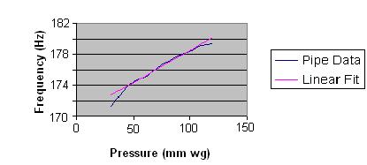
There is some argument over whether Baroque organ builders encouraged or tried to suppress transients, but as time moved on there is no doubting the dislike they engendered during the Romantic period of organ building of the nineteenth century and into the twentieth. By that time the work of mathematicians such as Fourier and physicists including Rayleigh had led to a greater understanding of acoustics, and this was one reason why new voicing and regulating techniques were invented which enabled transients to be better controlled. Closer to the present day we seem to have rediscovered a liking for audible attack transients in many organs to the extent that they are often overdone to a ludicrous degree. There is no evidence whatever that the early and great organ builders such as Arp Schnitger and Gottfried Silbermann actively encouraged every pipe in their organs to hiss, chiff and spit in the unpleasant way that many neo-Baroque organs do. At the same time, an artistic modicum of audible transient on the occasional pipe can sound attractive. Taste, as in all other matters, is the issue here. An important factor governing the transient behaviour of an organ pipe is how close it operates to an overblowing regime. Anyone who has experience of blowing a wind instrument such as a recorder knows that it will fly to the octave or an even higher note if the player’s breath control and tonguing is inadequate. The painful squawks of aspiring clarinettists, illustrating that the instrument is only too prone to fly to the twelfth of the note played, is another reflection of the same problem. Exactly the same applies to organ pipes, and the voicer can adjust their transient behaviour by exploiting this. Basically, the issue reduces to adjusting the wind pressure at which the pipe speaks, and this is illustrated in Figure 7.
Figure 7. The variation of fundamental frequency with wind pressure for a flue pipe This is a graph of some actual measurements I made on a flue pipe speaking the F below middle C. The blue curve shows how its fundamental frequency (pitch) in the steady state phase varied slightly with wind pressure. At low pressures the pipe ceased to speak at all, but above this its frequency was accurately linear against wind pressure over a certain range, as shown by the pink line. Beyond a certain critical pressure however, a flue pipe will suddenly start speaking at the octave and the twelfth virtually simultaneously (recall that the octave and the twelfth are the second and third harmonics respectively). This is the case for an open pipe; a stopped pipe overblows to the twelfth only. Pipes which can be described as partially stopped, such as the Spitzflöte (Spire Flute) and Rohrflöte (Chimney Flute), sometimes overblow preferentially to other harmonics such as the fifth or seventh, and this sometimes gives them an attractive whisper or whistle as they come onto speech. The overblowing behaviour of the pipe used for my measurements is not actually shown in the figure, but it began suddenly once the blue curve started to deviate from its straight line character above 100 mm pressure. By adjusting the wind pressure existing just below the languid of a pipe (i.e. at the flue itself), the voicer can set where on the curve it speaks. If it sits well inside the straight line region of the curve it will be quite difficult to get it to emit a pronounced attack transient, because we have seen already that the transient consists of an initial burst of the partials associated with overblowing. On the other hand, if it is closer to the top of the curve it will be more likely to overblow as it comes onto speech and thereby emit an attack transient. The wind pressure at the languid of a particular pipe in a rank is adjusted in several ways, for example by inserting wooden plugs into the foot if it is a wood pipe. Or the foothole of a metal pipe can be opened or reduced by working the soft metal. It should be remembered, however, that wind pressure adjustments as described will also affect the power or loudness of the pipe, and this brings us to the subject of regulation which will be discussed in the next section of this article.
Other factors affecting the attack transient include the type of action and the type of chest on which the pipe sits. These govern how quickly the wind pressure rises as the valve opens and in turn they affect any tendency the pipe may have to emit a transient as it comes onto speech.
Figure 8. A slider chest
A conventional slider chest is shown at Figure 8, and the important point to note here is the groove or channel above the pallet valve and below the pipe feet. This encloses a substantial volume of air which acts as a cushion or buffer when the pallet opens, tending to smooth out the sudden inrush of wind into the pipes. The pallet in such a chest can be operated mechanically, pneumatically or electrically. Of these, only a well designed mechanical action with low or moderate pluck gives the player control over the rate at which the valve opens, thereby also giving him/her control over the way the pipe comes onto speech. Because if the valve opens suddenly the pipe will emit a more pronounced transient than if it opens more slowly. Those who have not experienced this on a mechanical action organ with a moderate amount of pluck have yet to complete their education. It is an important matter, because the ear assigns a high degree of perceptual importance to the rate of onset of a sound and any characteristic transient it might have. Presumably these features have been selected as important to survival as our brains evolved, and subsequently they became equally important to the sounds of music.
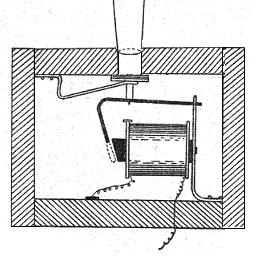
Figure 9. A direct electric unit chest By contrast, a direct electric unit chest of the type sketched in Figure 9 has no air cushion between the valve and the pipe. Moreover, because the action is electric in this case, the valve will always open more or less suddenly and its speed of opening cannot be controlled by the player. These factors will combine to produce an air impulse at the languid with a more rapid rise time than that produced by the slider chest, and the pipe will be prone to speak with quite a pronounced chiff or spit unless the voicer takes measures to reduce it. Therefore pipes voiced to speak on one type of chest may speak unsatisfactorily if transferred to another. Sometimes an expansion chamber is provided between the valve and the pipe foot in a unit chest to provide a speaking environment for the pipe more akin to that of the slider chest.
Besides adjusting where the pipe operates on the wind pressure curve of Figure 7, the voicer can also reduce the attack transient by cutting grooves or nicks in the languid. These encourage the rapid formation of turbulence in the air flow as it emerges from the languid, and the consequent randomisation of any noticeable transient effects that might otherwise occur.
Adjustments of the wind pressure existing at the languid of a pipe are more often made to regulate its power rather than to specifically tailor its transient behaviour, and this extremely important operation is therefore called regulation. The overall effect of an organ is determined at least as much by its regulation as by the timbres of the individual stops and the pipe scales. This is because regulation varies the power across the compass of each stop and how it compares with the powers of other stops.
Regulation is most often done by altering the size of the foot hole as described already, and it is worth noting that foot holes need to be surprisingly large if they are not to reduce the wind pressure at the languid at all - a foot hole with a cross-sectional area 3 times that of the flue slit will still reduce the pressure at the flue by about 10%. The alternative regulation technique, ubiquitous until about the mid-18th century and sometimes used again today, leaves the fully-open foot holes alone so that the full wind pressure in the chest appears at the languid itself. The power of the pipe is then regulated by adjusting the width of the flue, by working the soft metal of the pipe. Obviously, such an operation is much more difficult for wood pipes. Leaving the feet of the pipes unobstructed can endow an organ with considerable liveliness and character in some circumstances. This is because the speech of the stops in such an instrument varies markedly from pipe to pipe in terms of their attack transients, Incidentally, all this shows how difficult (often impossible) it can be to recover the speech of an old organ that has been altered. Even if the pipes remain in exactly their original condition with all the original foothole plugging etc intact, which is as rare as hens’ teeth, they may have been planted on a different chest with different sized holes in the top board, table and slider. Unless the wind pressures at the languids, not merely at the feet, of all the pipes can be exactly recovered, a restored or reconstructed organ cannot possibly sound as it did originally regardless of the hype foamed about it. Thanks are due to the church authorities at Malvern and Ponsbourne who allowed the acoustic measurements to be performed, and to Brian Daniels, organ builder, for permission to reproduce the spectrum of his quintaton stop. 1. “Gleanings from the Cash Book: St Mary’s Hatfield: Church Expenses”, P Minchinton, Organists’ Review, May 1999, p 108 2.
“The Effect of Wall Materials on the Steady-State Acoustic Spectrum of
Flue Pipes”, C P Boner and R B Newman, J Ac Soc Am, July 1940, p 83 3. “Sounds of Music”, C Taylor, British Broadcasting Corporation 1976, ISBN 0 563 12228 5 4. "The Art of
Organ-Building", G A Audsley, New York 1905, chapter IX. (republished Dover
1965, ISBN 0 486 21314 5). 5. "A Second in the Life of a Violone", C E Pykett, currently on this website (read). 1. “End Corrections of Organ Pipes”, A T Jones, J Ac Soc Am, January 1941, p 387 2. “Acoustic Spectra of Organ Pipes”, C P Boner, J Ac Soc Am, July 1938, p 32 3. “The Physics of Organ Pipes”, N H Fletcher, Scientific American, January 1983, p 94 4. “Voicing Adjustments of Flue Organ Pipes”, A W Nolle, J Ac Soc Am, December 1979, p 1612 5. “St Barnabas Church Dulwich, the tonal concept”, W McVicker, The Organbuilder, Vol 16 1998, p 8 |