Electromagnets and solenoids in electric actions for pipe organs - some design issues
Colin Pykett
"God
runs electromagnetics on Monday, Wednesday and Friday by the wave theory, and
the devil runs it by quantum theory on Tuesday, Thursday and Saturday"
Sir
Lawrence Bragg
Posted: 20
February 2015
Revised: 3
March 2015
Copyright © C E Pykett 2015
Abstract.
This article surveys the main types of electromagnets and solenoids used in
organs with an electric action. Emphasis is placed on a range of
fundamental design issues including magnetomotive force and the ampère-turns
product, the magnet core and the magnetic circuit. These are illustrated
with reference to three types of magnet used widely in organ building - lever
magnets, those with hinged or floating armatures and solenoids. Operating
characteristics are also presented which show how the force exerted by these
magnets varies with the position of the armature during its stroke. These
data are not widely available elsewhere, most manufacturers merely quoting a
single force figure if it is quoted at all. Considering that the force of
some magnets can vary as the cube of armature position, this approach is plainly
unsatisfactory.
Contents
(click
on the headings to jump to the desired section)
Introduction
History
Design
issues
A
simple electromagnet
The
ampère-turns product
The
core
The
magnetic circuit - Hopkinson's law
Armature
Operating Characteristics
Lever
magnets
Magnets
with floating and hinged armatures
Solenoids
Concluding
remarks
Notes
and References
Introduction
Electromagnets are the components which set electric actions for pipe organs apart from any other type, and they are used in large numbers in the smallest electric instruments.
So if Bragg was correct in his quotation above, it's a pity that neither God nor
the devil oversees their operation on Sundays, the very day that church
organists expect them to work. Each key will have one if the organ is 'straight' and uses slider chests, whereas each pipe will have one if it is fully unified as in the theatre organ. They range from the small, low power consumption types in electropneumatic actions where the heavy work is done by pneumatic motors, to larger and more powerful ones in so-called 'direct electric' actions where the magnet itself opens the pipe valve. Sometimes the core of the magnet is fixed in position and attracts an external moveable armature of some kind, while in other designs the core itself moves within the coil in the type of magnet known as a solenoid.
This article outlines the design features of the various types of magnet used in organ building. In particular, it addresses the magnetic circuit of an electromagnet because this is just as important as the electrical circuit which drives the coil, yet it is perhaps less well understood. The force versus armature displacement characteristic is also described, as this varies depending on the type of magnet and it is therefore important to match it properly to the intended mechanical load. Other topics include magnet efficiency, which is closely related to its 'pulling power' for a given electrical input. Efficient magnet design is particularly important in those applications where the magnet must exert a large force. These include direct electric actions where the magnets have to open pipe valves of substantial size against the wind pressure, and stop actions where large solenoids are sometimes used to move the sliders.
The article is written in descriptive and practical rather than theoretical terms, thus it avoids all but the simplest mathematics.
History
The electromagnet was first demonstrated by William Sturgeon in England in about 1824 and improved by the American Joseph Henry a few years later. However it is fair to say that until Robert Hope-Jones burst onto the British organ building scene in 1890, the application of electricity to organ actions was characterised more by ignorance and amateurism than anything else, apart from a few exceptions. David Hemsley has written a detailed account of the history of electric actions prior to that date
[1] which justifies this perhaps iconoclastic statement as fact. However he also pointed out that there were good reasons for it, which lets organ builders off the hook to some extent. Hemsley quoted an example typifying the woolly thinking of the mid-Victorian era which saw difficulties in coping with the varying numbers of magnets energised during the playing of a piece - it was assumed by some that the current drawn from the battery would always be the same, thus when only a small number of magnets were in use they would consume the same total current as a larger number. A major design problem, according to this view, was therefore to construct magnets which could cope with the total current should just a single one be
energised. A non-problem if ever there was one! Therefore Ohm's law was clearly not part of the stock in trade of all organ builders at that time even though it had been published before 1830. Nor was Hopkinson's law, the analogue of Ohm's law for magnetic circuits, which appeared later. Given this unpropitious background, it is not surprising that many magnets used in these early actions did not approach optimal efficiency in any respect.
Hope-Jones, though, was a professional engineer, and within the somewhat secretive confines of his own organ building practice he swept away this miasma of confusion. Regrettably, he replaced it with his own brand of deceit which continues to reverberate to this day in that some are still taken in by it. For instance, it was he who claimed that his largest organs would work for several months on a single dry cell, a blatantly untrue statement which I have discussed elsewhere
[2]. Nevertheless, hindsight enables us to separate fact from fiction more readily, and today it is apparent that he was a very good engineer who made genuine advances in circuit techniques and electromagnet design, indeed the ubiquitous 'action magnet' used worldwide in electropneumatic actions still remains almost in the form he patented it in 1891.
Design
issues
A simple electromagnet
The simplest possible electromagnet consists merely of a coil of wire as illustrated in Figure 1.
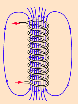
Figure 1. Illustrating the magnetic field produced by a coil of wire
Such a coil is called a solenoid, and the diagram illustrates the magnetic field configuration it generates when a current passes through. This simple arrangement will act as an electromagnet, though not a very efficient one, in that it will attract an iron object placed close to one end if the current is strong enough. The strength of the attraction depends on the field density or magnetic flux within the solenoid, and it is a useful abstraction to regard this as proportional to the number of lines of force passing through the winding. The number of lines, or flux, can be increased by increasing the number of turns on the coil, by increasing the current passing through it, or by inserting a core of suitable material into the solenoid. These parameters will now be discussed in more detail.
The
ampère-turns product
Flux is proportional both to the number of turns
(N) and to the current (I), though it is not possible to consider these parameters in isolation because they depend on each other -
I decreases as N increases because more turns increase the coil resistance and thus decrease the current, and vice versa. Therefore their product
NI is the parameter which is optimised, and it is called the 'amp-turns' product of a magnet, because current is measured in
ampères. It is important to maximise the amp-turns product for a magnet supplied with a given voltage so that the force exerted by the magnet, and thus its efficiency, will also be
maximised.
The current I is defined by Ohm's law as V/R, where V is the applied voltage (assumed here to be a given) and
R the resistance of the coil. R depends on the total length of wire, and thus on the number of turns
N. It also depends on the wire gauge, that is, its diameter. Therefore it is not obvious at first sight how to maximise the
NI product, because increasing the number of turns will increase N but decrease
I as we noted above. In an ideal world, the amp-turns value will continue to increase indefinitely as the wire diameter increases. Even though this reduces the number of turns, because thicker wire means that fewer turns can be accommodated on a given winding bobbin or coil former, the fact that the current can increase indefinitely whereas the number of turns cannot means that the magnet gets progressively more powerful as turns are removed from the coil - provided the necessary current can always be supplied. This behaviour is illustrated in Figure 2.
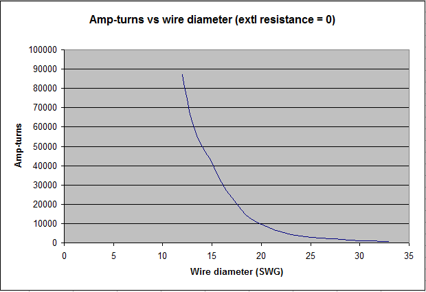
Figure 2. Theoretical variation of amp-turns product with wire gauge for a given electromagnet coil former - no external circuit resistance assumed
Wire diameter here is plotted in terms of UK Standard Wire Gauge (SWG). It can be seen that there is no peak on this curve indicating an optimum amp-turns value. However it is of little practical interest in this application for other reasons, because the current at the largest wire diameter considered would be 2654 amps at a coil voltage of 15 volts! (This calculation was done using the bobbin dimensions of an actual magnet discussed later and shown in Figure 5). Nevertheless, where enormous fields have to be created such as in MRI scanners, massive currents circulate continuously through coils cooled close to absolute zero, at which temperature superconductivity then takes place.
In less exotic applications, currents of this order could not be drawn even if the power supply was up to it because there will always be some external circuit resistance. Quite small values dramatically alter the situation, as shown by the curves in Figure 3.
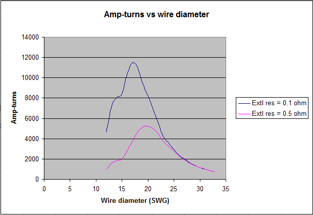
Figure 3. Theoretical variation of amp-turns product with wire gauge for a given electromagnet coil former - two values of external circuit resistance assumed
Curves were plotted for two typical values of external resistance, 0.1 and 0.5 ohms, and it can now be seen that the data indicate some sort of optimum wire diameter on the face of
it in each case. (The discontinuities in the curves corresponding to wire diameters around 15 SWG arose from the granularity of the SWG values themselves. At such small values of external circuit and coil resistance, the arithmetic gets very critical). Even so, the corresponding currents at these peaks
are still far too large to be practical, but there is another reason why these amp-turns values could not be used. This concerns core saturation, which will now be discussed.
The
core
For DC electromagnets the core is usually of 'soft' iron, often Swedish iron. It, or another suitable material such as silicon steel, has the essential characteristic that it retains negligible residual magnetism when the current is turned off. This was sometimes a problem in early action magnets such as those of Hope-Jones, which controlled a tiny armature moving no more than 0.5 mm and with no return spring. The problem may have been exacerbated by the difficulty in his day of maintaining the metallurgical properties of the material within sufficiently close tolerances.
In effect, the core concentrates the lines of the magnetic field generated by the coil, thus increasing the flux. The factor by which it is increased is termed the permeability of the core, and it can take values of several thousand. However an important point is that any core other than air will eventually saturate at a particular value of applied field, in that a further increase (that produced by a larger amp-turns value) will produce little further increase in flux. This is shown graphically in Figure 4.
Figure 4. Variation of flux density
B and permeability µ in an electromagnet core with applied magnetic field
H
The applied field produced by the amp-turns value of the coil is denoted by
H and the resulting flux induced in the core by B. Permeability is written conventionally as
µ (the Greek letter 'mu'), thus B = µH according to the definition above. Beyond the approximately linear region of the curve the rate of rise falls off, and eventually it reaches a plateau when the core saturates. For the same reason, the permeability is not constant but decreases sharply after it reaches a maximum value
µmax .
Therefore a magnet should be designed so that it operates at an amp-turns value which takes the core fairly close to saturation, and the obvious choice is that which corresponds to
µmax . If this is not done by design, the magnet will not be as powerful as it could be for the chosen core and thus it will not be optimally efficient. However
when it is done, it means that the magnet cannot then be made significantly more powerful by increasing the applied voltage (and thus the current), as then the core will be driven into saturation. For properly designed organ magnets this is why a 15 volt magnet, say, is not much more powerful when operated on 24 volts - it merely gets a lot hotter because (by Ohm's law) the power dissipated in the coil is proportional to the square of applied voltage.
Thus the core characteristics often define the maximum amp-turns value which can be used in
practice because of saturation. A bobbin design then has to be dimensioned which will generate this value with wire of the appropriate diameter, and simultaneously result in a coil having the necessary resistance for the operating voltage available. Thus magnet efficiency depends on synergism - all these parameters (optimum permeability, optimum amp-turns, wire gauge and coil resistance for the chosen operating voltage) being mutually optimised in a particular design. Computer design tools such as those used here are essential to do a proper job.
The magnetic circuit - Hopkinson's law
The outermost field lines drawn at the extremities of the sketch at Figure 1 suggest that some of the lines originating at each end of the coil can in fact close, and this brings us to the important topic of optimising the magnetic circuit of an electromagnet. Unless the field existing at each end of the core is used to operate the armature, a lot of flux is lost because the majority of the lines do not close and the magnet will be inefficient. Therefore magnets are designed to direct the flux from both ends of the coil towards the armature. An example is the lever magnet used widely in organs, one form of which is pictured in Figure 5.
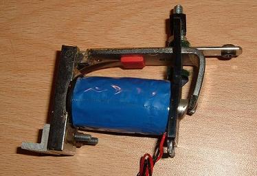
Figure 5. A lever magnet used in direct electric actions
This example is a relatively powerful magnet used to open pipe valves directly in a so-called direct electric action, instead of using a pneumatic motor to do the heavy work as in an electropneumatic action. It can be seen that the flux from the left hand end of the core is directed through a substantial baseplate and the armature itself to meet that from the pole piece on the right. This forms the magnetic circuit of the device.
In some ways magnetic circuits are analogous to electric circuits, but with the difference that nothing actually 'flows' with time in the magnetic one in the same way that there is electron
drift in the electric one. Therefore no power is converted to heat for DC electromagnets in the magnetic analogue of resistance, as happens with electric circuits. Nevertheless there is a magnetic analogue of resistance, and it is called reluctance.
Reluctance appears in the magnetic equivalent of Ohm's law used for electric circuits. Ohm's law is written as:
EMF = RI
where
EMF is the electromotive force or voltage applied to the circuit, R is the total resistance and
I is the current flowing.
By analogy, the magnetic equivalent of Ohm's law is called Hopkinson's law and it is written as:
MMF =
Rel B
where
MMF is the magnetomotive force applied to the magnetic circuit, Rel
is the reluctance and B is the magnetic flux within the circuit.
MMF is measured in units of amp-turns, the NI product we met earlier, and flux
B is proportional to the density of the field lines 'flowing' through the circuit. However it is usually less than the magnetic flux induced in the core of the electromagnet because of flux leakage which occurs at various points around the circuit - lines of force effectively leak out, especially if there are physical gaps. In the magnet of Figure 5 there is always a gap between the moving armature and the core regardless of the position of the armature, and this makes lever magnets less efficient (and thus less powerful) than some other types in which this gap is closed when the magnet is
energised.
In the lever magnet the gap never closes.
Reluctance is important because the applied magnetomotive force causes most of the magnetic flux through the circuit to take the path of least reluctance. This is similar to an electric circuit in which the applied electromotive force causes most of the current to take the path of least resistance. Therefore efficient magnet design means that reluctance has to be
minimised. One way to do this is to ensure that all parts of a magnetic circuit are constructed from material with a substantial cross-sectional area, just as low electrical resistance demands the use of thick wire. For AC transformers for example, the core area required is proportional to the square root of the power to be transferred from the primary to the secondary winding. With experience, one can tell just by looking at it whether an electromagnet will be efficient or not - flimsy-looking magnets are not going to be very powerful because they do not allow sufficient flux density to develop within their magnetic circuits.
All electromagnets exhibit a variable value of reluctance throughout their operating cycle. If they did not, the armature would not move. This is because the armature will move such that the reluctance of the magnetic circuit is minimised (or until it is physically prevented from moving further, beyond an end stop for example). Therefore the armature in the magnet of Figure 5 will slide over the pole piece when current is applied, meaning that the reluctance of the magnetic circuit changes from an initially high value to a lower one as the movement takes place. This accords intuitively from what we can see from the picture.
With the armature in the position shown, there is obviously gross flux leakage from the exposed pole, though some of these leaking field lines will link with those 'coming out' of the armature itself - these arose originally from the opposite pole and then passed through the magnetic circuit. Consequently they exert a force on the armature, which becomes zero when no further reduction in leakage (and thus of reluctance) can take place.
It will therefore be appreciated that the force experienced by the armature is not constant during its operating cycle, because it attempts to move until the net force on it becomes zero. The variation of force with armature position differs for different types of magnet, and this important characteristic will now be explored.
Armature operating
characteristics
The armature operating characteristic is a curve which shows how the force exerted on an external mechanical load by the armature varies as the armature moves towards the position of minimum reluctance when the magnet is
energised.
The characteristic differs dramatically for different types of magnet, and it is important to choose the best characteristic for a given application in organ building. A point to bear in mind is that, although the armature of any magnet always moves to minimise reluctance, the force available to the load can either increase or decrease towards the final armature position depending on the particular type of magnet. Perhaps surprisingly, data on the operating characteristics of electromagnets are not always provided by their manufacturers, therefore the subject will now be discussed in some detail.
Lever magnets
A
typical 'heavy duty' lever magnet was pictured at Figure 5. The pulling force versus armature position characteristic of this unit was measured using the method to be described.
The magnet had a 30 ohm coil and it was specified for operation at 15 volts, which was provided by a stabilised DC power supply. It was clamped in a vice 'upside down', i.e. so that its armature pulled upwards when the magnet was
energised. This was opposite to the usual mode of operation which would normally be used in an organ in which the armature pulls a pallet or other form of valve downwards. This orientation was used so that the force exerted by the armature could be measured easily by adding small weights to a scale pan of known weight, hung from the bush attached to the armature through which a pull-down wire would normally pass.
As supplied, the armature had been adjusted by the makers so that there was a total movement of about 6 to 7 mm, though there was some uncertainty in this value owing to the use of thick felt end stops at both extremities of travel. When the magnet was energised continuously it was obvious, merely by moving it by hand, that the position of the armature in its rest position (i.e. its position when the magnet was not
energised) was at or very near the cusp of a pronounced nonlinearity of the force versus position curve. At this cusp the pulling force of the magnet was maximum and the force fell away
on either side. The unenergised position of the armature was therefore critical if the maximum pulling force was to be available for breaking the pluck of a valve against the wind pressure ('pluck' being the force exerted by the organ wind pressure against the valve before it opens. Pluck vanishes once the valve starts to move). The armature had been approximately so adjusted in the magnet as supplied, but the maximum force could be increased in the sample obtained by about 30% by more careful adjustment. Owing to the criticality of the adjustment this might lead to less reliable operation in an organ however, and it might not therefore be advisable.
To establish the nature of the armature operating characteristic in more detail, the magnet was energised continuously and its maximum pulling force was first established. Sufficient weights were added to the scale pan such that the armature was not observed to move at all when power was applied to the magnet. Weights were then removed carefully with a minimum increment of about 3.5 gm until the armature was just observed to move slightly away from its rest position. Additional weights were next successively removed to allow the armature to move towards the pole piece of the magnet in steps of about one
millimetre. At each of these points the scale pan was slightly 'bounced' several times by hand to allow it to settle in a reproducible position.
The graph in Figure 6 shows the results.
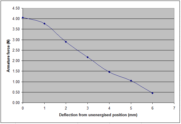
Figure 6. Armature operating characteristic for a lever electromagnet
Within the limits of experimental error, it can be seen that the pulling force of the magnet reduced almost linearly as the armature moved towards the pole piece. This is a characteristic well suited to breaking the pluck of an organ windchest valve. The amount of armature movement, around 6 or 7 mm, is also well suited to the amount a typical disc, cone or pallet valve needs to descend in order to create a reasonable
windway. However the nature of this characteristic will be partly due to the armature return spring in the magnet, which exerted a force which increased with deflection.
When the magnet is used in the more conventional manner in which it pulls a load downwards rather than upwards, it would be expected that the force at all points would be greater by an amount equal to twice the effective weight of the armature at the point of measurement (the pull-down bush). This is because, in the experiment here, the armature weight was acting against the magnet whereas when mounted in the normal way its weight would assist the magnet by the same amount.
There will also be a dominant effect due to the geometrical variation in the magnetic field configuration between the bevelled magnet pole and the armature as the armature moves. The field lines before the armature begins to move will be more nearly aligned parallel to the bevel of the magnet pole than when the armature is at the opposite extremity of its travel. In this latter case the field lines will be aligned almost perpendicular to the bevel. This variation will obviously result in a corresponding variation of the pulling force of the magnet resolved as a vector along the armature. This is the main reason for the characteristic observed in this experiment. It also explains the variation in magnetic reluctance (largely due to flux leakage) with armature travel, and thus demonstrates how the armature of an electromagnet moves from a position of high reluctance to one with a minimum value - assuming it can reach that position without encountering an end stop.
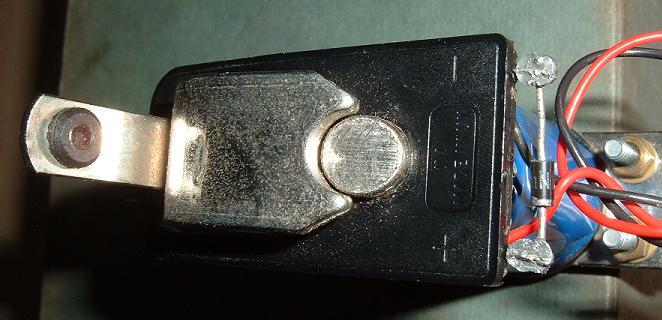
Figure 7. Cut-away armature on a lever magnet
Another factor is worth mentioning, in which the armature of this magnet was cut away to correspond with the circular profile of the adjacent pole piece. This is illustrated in Figure 7. If this were not done, thus leaving the armature with a squared-off edge, part of it would always be occluding the pole piece even in the unenergised position. We have noted already that the force acting on the armature before it begins to move is a function of the magnetic field geometry between pole and armature. Therefore the force would be reduced if any part of the field was perpendicular to the pole piece, because the force exerted in that region could not be resolved as a non-zero vector in the orthogonal direction, that is, along the length of the armature. If the pole had been rectangular in cross section, the armature need not have been cut away of course.
Overall, the armature operating characteristic of this magnet is therefore well suited to the nonlinear force versus position attribute of an organ valve with pluck when working against wind pressure.
Magnets with floating and hinged armatures
Lever magnets are not found often outside the world of organ building. Besides the characteristics just described, another desirable attribute is that they are noiseless because the armature does not contact the magnet pole at any point in its travel. Lever magnets also have an intrinsic and useful 'long-throw' characteristic because of the
approximately linear, rather than a power law, nature of the operating characteristic. These desirable attributes are not found in the more conventional type of electromagnet in which a floating or hinged armature is attracted to the magnet poles to ultimately contact them. Such magnets are potentially noisy unless they are operate at very low power.
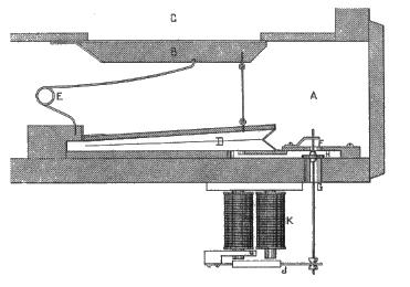
Figure 8. Hinged armature electromagnet
Notwithstanding the noise problem,
these magnets were the sort first tried in early electropneumatic actions in the nineteenth century and an example is shown in Figure 8. This was designed by Albert Peschard in the late 1850's
[3] and further details of this and similar ones can be sought from Hemsley's research
[1]. The armature is hinged on a flat return spring and it contacts both pole pieces when the magnet is
energised. The magnetic circuit is U-shaped, thus the circuit is complete and reasonably efficient when the magnet is
energised, though the air gap at intermediate armature positions results in a dramatic loss of
efficiency which reflects into the operating characteristic. Such magnets were coming into widespread use at that time in telegraph systems and electric bells, for example.
The armature operating characteristic of this type of magnet is the inverse of that for the lever magnet in that the force increases, rather than decreases, as the armature moves away from its unenergised position. Despite this major difference the magnets are similar in that the armature in both cases moves to minimise the reluctance of the magnetic circuit. A typical operating characteristic is illustrated in Figure 9.
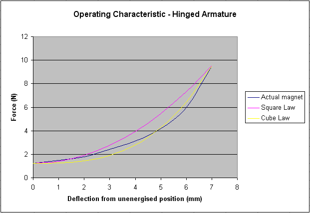
Figure 9. Typical operating characteristic for a hinged armature
Thus the force increases rapidly as the gap between the armature and the poles decreases, and it is commonly assumed that it follows an inverse square law versus air gap. This is not always so however, as these data actually fitted a cubic law more closely as Figure 9 shows. When the armature is fully engaged with the pole pieces, magnets of this type are fairly efficient in that little flux leakage occurs, and the force required to pull the armature off the poles exceeded 9 N in this case (corresponding to a substantial weight of well over 900 gm or 2 lbs). But at the point the armature began to move it only exerted a pull of about 1.5 N on account of the large air gap with its consequential flux leakage. Therefore this type of magnet does not have the long-throw capability of the lever magnet, and its other characteristics such as noise make it ill-suited to most applications in organ building.
An important exception to this generalisation is found in the ubiquitous 'action magnet' or 'chest magnet' used in electropneumatic actions. This was developed into pretty much its present form by Hope-Jones in the 1890s, who took the unnecessarily large, noisy and powerful magnet shown above and derived a miniaturised and elegant version of it. An example of a modern chest magnet is pictured in Figure 10.
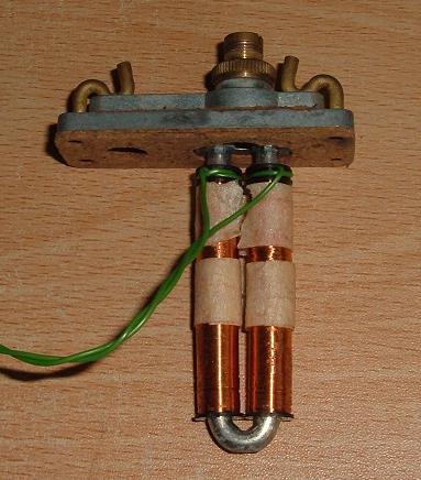
Figure 10. A modern chest magnet used in electropneumatic actions
The small and lightweight disc armature (not visible) also acts as a two-way valve which either exhausts a pneumatic relay motor to the atmosphere or inflates it with pressure wind from the chest, depending on whether the magnet is energised or not. The
reason why it is not visible is because it is enclosed in the removeable housing
at the top of the picture, hinged on a light phosphor bronze flat spring. However the armature in Hope-Jones's original design was completely floating, relying only on wind pressure to blow it against the adjustable exhaust tube when the magnet was not
energised. This was probably one reason why his chest magnets were sometimes prone to unreliability due to residual magnetism in the core, especially when the wind had just been turned on and the armatures were still sitting under gravity on the magnet poles. Interestingly, some organ supply houses have returned recently to the original Hope-Jones concept of a floating rather than sprung armature.
These magnets consume little power, that shown drawing about 0.1A from a 15 volt supply. The lightweight armature only moves a millimetre or two, thus for these reasons there is no noise problem in practice as there would be with a larger magnet of similar design.
Solenoids
In common parlance and understanding, solenoids are different from the electromagnets described so far even though the coils on all types of magnet are sometimes referred to as solenoids. Therefore we shall avoid this confusion by defining a solenoid as one which has a plunger-type armature which is drawn into the coil when it is
energised.
As with electromagnets generally, the solenoids available on the wider industrial market are seldom suitable for use by the organ builder because they are far too noisy. An example is shown in Figure 11.
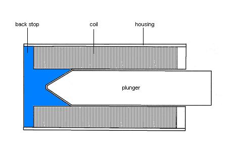
Figure 11. Typical industrial solenoid with back stop
This has an iron or silicon steel back stop which the plunger, made of the same material, meets forcefully when it is drawn fully inside. Although these devices can be efficient and powerful, think of vending machines or car door locks to recall the sort of racket they kick up. Therefore organ solenoids seldom have the back stop fitted, although they are otherwise similar even down to having plungers with the tapered ends shown in the drawing. In this article only solenoids without a back stop are considered.
For reasons of efficiency (minimising flux leakage) it is highly desirable to enclose the coil in a cylindrical housing as shown. The housing is made of the same high-permeability material as the plunger, and it completes the magnetic circuit in conjunction with the two circular end pieces. One only has to experiment with a solenoid without its housing to realise what an important function it performs. It captures the field lines which would otherwise escape beyond the coil and confines them within the magnetic circuit.
If the plunger is smaller than the length of the solenoid, it will come to rest symmetrically in the centre when power is applied, provided it is not constrained mechanically from doing so. This is the position of least reluctance, which increases if the plunger moves away to either side. Therefore solenoids offer an arbitrarily long throw capability in that it is only necessary to provide a sufficiently long solenoid for the length of plunger travel required. The length needed is typically at least three times the useful throw length, that is, the length over which a useful operating force is available. Long throw is a major advantage of the solenoid over other forms of magnet.
The force exerted on the plunger increases rapidly as it is drawn towards the central (minimum reluctance) position, and this is illustrated in a typical operating characteristic shown in Figure 12.
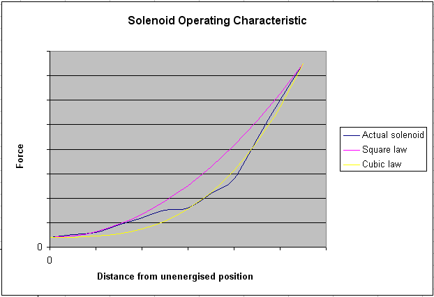
Figure 12. Generic solenoid operating characteristic
The blue line here depicts generic data representing a range of solenoids, hence the absence of numeric values on the axes. This is because of the very wide range of variants which can exist in practice. As well as parameters common to all electromagnets such as amp-turns and operating voltage, solenoids also have
important design attributes including coil length, plunger dimensions, throw length, and the type of taper applied to the plunger ends. Any and all of these affect performance markedly. Thus an attempt has been made to normalise for them to produce the generic curve shown here.
As with the hinged and floating armature magnets discussed earlier, it can be seen that the force exerted on the plunger varies rapidly with its position inside the solenoid, the curve lying fairly close to a cubic law over the most useful operating range
(medium to high force) as the plunger approaches the centre. The horizontal axis represents the distance of the plunger from an initial position nearly outside the coil before the solenoid was
energised. Thus maximum force was obtained when the plunger had moved to a position symmetrical about the centre of the winding. Whether the minimum force for a particular solenoid
indicated here would be useful in practice is another matter because it plainly reduces rapidly as the plunger withdraws, but the distance between the two extreme plunger positions is typically about half the coil length. This confirms that solenoids have an intrinsic long-throw capability which can be tailored to a specific application by designing a unit (together with its plunger) of the correct length.
Solenoids find several applications in organ building. They are used to operate motorised drawstops in combination systems for example, and in this application they are double acting so that the stop head can be thrown in or out as required for a given piston setting. Two solenoids with a common plunger are mounted back to back for this purpose, and each will typically consume 0.5 A from a 15 volt supply. Throws vary between 15 and 25 mm in either direction depending on the unit chosen by the organ builder. With combination systems in which power is applied to the solenoids for as long as a piston remains pressed, it is possible to get an idea of the pronounced variation in force with plunger position by
pushing the head of a drawn stop by hand against the force of its solenoid.
(Do not try to pull them, as the stop head might come off!). This test cannot be done if the
combination system only pulses the coils briefly, however.
At the other end of the scale powerful solenoids, again double acting ones, are used to operate the sliders in bar and slider chests. These have a resistance of only a few ohms, so they consume currents of several
ampères. Manufacturers' data sheets sometimes do not give more than minimal information about them, such as vague statements that they have a pulling force of 50 N or
so, a typical figure. Thus is it not clear at which point on the throw this force is available, and how it varies with plunger position. The situation is complicated by the electronic control systems used, which are often sourced from manufacturers different to those which made the solenoids. These commonly vary the applied electrical power during the throw, it being greatest when first applied and then tapering off afterwards over a power-pulse time of about 250
milliseconds. In principle this technique can linearise the operating characteristic if the current taper is carefully optimised in conjunction with a particular solenoid, but in practice the aim is more to reduce noise than anything else as these powerful slider solenoids can be unpleasantly noisy otherwise. They have throws up to about 30 mm each way. In neither of the applications just described could any other form of magnet provide this level of performance, particularly regarding the throw lengths mentioned.
Concluding
remarks
This
article has surveyed the main types of electromagnets and solenoids used in
organs with an electric action. Emphasis was placed on a range of
fundamental design issues including magnetomotive force expressed as the ampère-turns
product, the magnet core and the magnetic circuit. These were then
illustrated with reference to three types of magnet used widely in organ
building - lever magnets, those with hinged or floating armatures and
solenoids. Operating characteristics were also presented
which show how the force exerted by these magnets varied with the position of
the armature during its stroke. Such data are not widely available
elsewhere, most manufacturers merely quoting a single force figure if it is
quoted at all. Considering that the force of some magnets can vary as the
cube of armature position, this approach is plainly unsatisfactory.
Notes and References
1. "Henry Bryceson (1832-1909), organ builder, and early work in the application of electricity to organ actions", J D C
Hemsley, PhD thesis, July 2005, Cardiff University of Wales.
2. "Hope-Jones and the dry
cell", an article on this website, C E Pykett 2003.
3. "Les Premières Applications de l'Électricité aux Grand Orgues", A
Peschard, Paris, 1890.