


|
|
|
Winston Kock and the Baldwin Organ by Colin Pykett Posted: 5 November 2008 Last revised: 1 October 2017 Copyright © C E Pykett Abstract. Winston Kock was and remains well known to niches of the global science and engineering community for his work in several areas, including acoustic holography and meta-materials. He occupied a number of senior positions during his career in industry, academia, NASA and Bell Telephone Laboratories.
The Baldwin electronic organ which appeared just after the second world war was and remains well known to many in the global electronic music community. It pioneered a number of entirely new techniques which were used in the majority of electronic organs for half a century until analogue technology was eventually superseded by digital.
However the link between the man and the instrument is less well known. In fact Kock invented the Baldwin organ as a young engineer before moving into other areas. Therefore the purpose of this article is historical and twofold: it summarises the life and work of Kock in electronic music, and it also describes the important features of the Baldwin organ which resulted from his early research.
Contents (click on the headings below to access them) The man pictured above, probably circa 1950, is Winston Kock. How many readers will know the name? Without knowing the answer to this question, I suspect nevertheless that not many will. Yet he invented most aspects of the original Baldwin analogue electronic organ before the second world war, a design which set a standard which most others aspired to but seldom achieved for many decades until the field was overtaken by the digital revolution. He also composed music and wrote novels. But despite all this, he was best known to the professional electronics community in areas outside these because he was also the Director of Acoustics Research at Bell Telephone Labs in the USA, and subsequently he became the Director of NASA’s Engineering Research Center. Throughout a long and distinguished career he was closely associated with many of the great names in electronics, such as the Nobel prize winners Bardeen, Brattain and Shockley who invented the transistor. The above is just a snapshot of the life of a man with talents beyond the ordinary, and because his contributions to electronic music were overshadowed by those he later made in other areas – scarcely a criticism – it is worth looking in more detail at the early part of his career, and in particular how it led to the birth of the Baldwin organ. Winston Kock was born in 1909 in Cincinnati, Ohio, a Midwestern state bordering the Great Lakes in the engineering heartland of the USA. Earlier generations of his family had probably immigrated to America from Germany. His was a comfortable background which could probably have maintained him in an existence of leisure and passivity had he been so inclined. However there is no doubt that the support and interest shown by his parents in nurturing the talents of their gifted son was a significant factor in his development, and he remained intellectually vigorous and active throughout his life [1]. While still at school he distinguished himself by playing at least one complete piano concert entirely from memory, and shortly thereafter he began to compose music. But he studied electrical engineering, not music, at Cincinnati university and in his 20’s he designed a fully electronic organ (i.e. not an electromechanical one as were the contemporary Hammond and Compton Electrone). This was accepted as part of his Master’s degree because almost everything in it was entirely new at that time. As a fresh-faced 23 year old he appeared on the front page of a Cincinnati newspaper playing it in 1932.
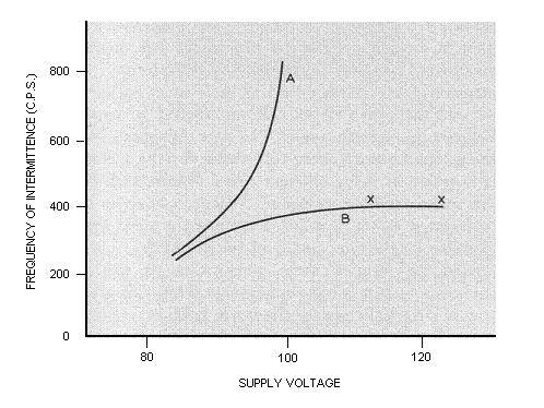
The frequency stability of analogue oscillators was a major problem in electronics in the 1920’s and 30’s, but an even more pressing one was cost. Despite the heroic efforts of Coupleux and Givelet in France, you simply could not build a commercially viable organ using the necessary large numbers of thermionic valves (vacuum tubes) in those days because they were so expensive, regardless of whether they could do the job or not. It was these problems of cost and technical inadequacy which drove clockmaker Laurens Hammond in the USA to develop his electromechanical tone wheel generator system for the Hammond organ. A similar approach was adopted by Leslie Bourn and Wallace Fair at about the same time in the UK for the Compton Electrone, though their rotating discs used an electrostatic rather than an electromagnetic principle of operation. This distinction was probably forced on them by Hammond’s patents as much as anything else. But the young Winston was undeterred by the shortcomings of the electronic technology of his day, indeed in it he saw several challenges. He decided to use neon gas discharge tubes as oscillators, which were not sufficiently stable on their own however. But they did have the necessary advantage of cheapness compared to valves, and they consumed far less power. His main innovation was to stabilise their frequencies using resonant circuits, and organs using neon oscillators and frequency dividers were still being marketed worldwide until at least the 1960’s by firms such as Kinsman. The curves shown here in Figure 1, published in 1934 both in his doctoral thesis and in the open literature, show the effectiveness of the techniques he developed.
Figure 1. Curves
showing the variation of pitch with voltage of the standard glow discharge
circuit (upper curve at A) and of Kock’s more stable circuit (lower curve B).
In the region X – X the change of pitch with voltage is extremely
small. The pitch of the
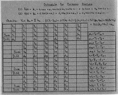
corresponding note would have been close to the G above 8’ middle C. It is worth asking ourselves how he actually carried out this work. For example, how would he have measured frequency accurately in those days? There were no electronic frequency meters with digital displays giving instant readings to several significant figures! I am not sure how he did it, but one possibility is that he used a siren which was a standard technique in its day. A siren is a rotating disc with holes near its periphery through which an air jet is blown. The pitch of the resulting musical note would be adjusted by ear for a zero beat condition against the sound of the oscillator under test emitted from a loudspeaker. The adjustment would have been done by varying the current through the siren motor using a rheostat. Knowing the rotation speed of the disc it would then have been possible to calculate the frequency of the siren and thus that of the signal under test. The rotation speed was calculated from the number of revolutions of the disc in a given interval, measured by means of a stopwatch and a mechanical counter attached to the siren drive shaft. We might also enquire how he observed the waveforms generated by his neon oscillators. Anyone involved in audio and electronic music needs to know what their waveforms look like if only to get their circuits working properly, and Kock must have achieved it somehow because some of his publications contain sketches of them. He also described the methods he used to analyse their frequency structure years before computers, FFT’s and the like were available. However, the oscilloscope had not yet arrived as a laboratory tool for routine use, thus about the only technique available to him would have been the use of the Duddell oscillograph or similar instruments. These used a mirror galvanometer to deflect a spot of light onto a rapidly moving photographic film which was subsequently developed. The sheer awkwardness, tedium and general difficulty of doing research in those days only becomes clear when we ask these sorts of questions, and they highlight Kock’s abilities as an R&D engineer, his determination and the originality of his results Kock’s organ design also contained the germ of a remarkably mature system concept considering he was still only a young student barely out of his teens when he began work on it. His concept reigned supreme until analogue organs were finally displaced by digital ones in the 1990’s, 60 years later, after the original Allen digital patents expired. He had obviously decided at this early stage in his career that tonal synthesis could only be done properly if sufficient harmonics were available to start with, rather than trying to build up the tones harmonic by harmonic using additive synthesis. Again, this was a decision based on engineering practicality rather than theory because there was nothing wrong with additive synthesis in principle – after all, it had been patented as an idea by Robert Hope-Jones as long ago as the 1890’s using rotating toothed wheels similar to those later used by Hammond [2]. The trouble was that it was impossibly difficult in practice and, again, too expensive to generate pure harmonics in sufficient numbers when all you had was neon oscillators, or rotating wheels for that matter. Hundreds if not thousands of tubes would be required for an additive synthesis instrument. But by generating, not sine waves, but waveforms containing lots of harmonics – Kock’s neon oscillators generated waveforms similar to sawtooth waves – you could filter out those you did not want. This concept was called subtractive synthesis, and although he did not invent it I believe it is reasonable to credit him with demonstrating it in a form suitable as a practical way ahead for electronic organs at this time. In the early 1930’s Kock went to Germany to study two main topics – improving the understanding of glow discharge (neon) oscillators, and developing realistic organ tones using specially designed filter circuits. On an Exchange Fellowship he went to the Heinrich Hertz Institute at the prestigious Berlin Technische Hochschule to conduct research for a doctorate under Professor K W Wagner. He was apparently fluent in German, possibly because previous generations of his family may have originated there. At that time Germany was leading the field in electronic music, with pioneers such as F Trautwein, Harald Bode and Oskar Vierling as well as Wagner himself. Wagner coined the term formant to describe the important fixed-frequency resonances which occur in certain musical instruments, and their variable-frequency counterparts in the human vocal tract. Like Kock, Bode later became well known in electronics more generally, pioneering several important techniques for filter design such as Bode Plots, but unlike Kock he also remained close to electronic music throughout his career. The Bode Melochord was an instrument with “travelling formants” which demonstrated the importance of having several tone filter circuits for each voice, each circuit covering only a section of the keyboard. Bode also collaborated with the late Robert Moog when he was designing the legendary Moog synthesiser of the 1960’s. As for Vierling, he invented the Electrochord in which the signals picked up from piano strings were processed to produce a range of quite different sounds, and Trautwein was responsible for the (rather curious) Trautonium. Kock duly obtained his PhD but he began to realise that an association with the Germany of that era was not advisable, especially as the Nazis were using his work to produce rabble-rousing musical sounds at their rallies. So he moved to India, spending a year at the Indian Institute of Music in Bangalore where he continued to study the design of tone forming filters for electronic organs. It is appropriate to pause at this point and review what was known at that time about the subject, and how difficult it was to make progress. We are speaking of the mid-1930’s at this point in the narrative. To design a tone forming filter for an analogue organ, you first need to know what the harmonic structure of the corresponding organ pipe looks like. Today we can simply do this by making a recording of the sound on the hard disc of a PC, and then analyse its frequency structure using a waveform editing program which offers a FFT (Fast Fourier Transform) facility. Lo and behold, a pretty harmonic spectrum in full colour jumps into view within less than a second. In those days there were no computers of any sort (the looming war forced their development), the FFT was a term not even coined until the 1960’s by Cooley and Tukey, and the only means to make a barely adequate sound recording was on a wax 78 rpm master disc (analogue tape recording was yet to be invented, again during the war) The recording process was so expensive and specialised as to make it unusable for most research purposes. Papers in the scientific literature were only just beginning to appear detailing the harmonic structures of organ pipes, notably by Boner in the USA [3]. He did this by having them sound continuously in front of a microphone while he manually scanned a tuned circuit across the audio range, laboriously noting the readings when a harmonic peak was encountered. It would have taken hours to analyse the sound of each pipe, particularly as he mounted them on top of a tower out of doors to achieve reasonably anechoic conditions. Nevertheless, Kock probably used these and similar early measurements to design his first really accurate analogue tone filters. He also knew more or less the harmonic structure of his neon tube waveforms, having determined such structure in two ways. Either he used Boner’s scanning filter technique, or he calculated the harmonic amplitudes by hand using Fourier analysis applied to measurements taken from a trace of the waveform on paper. Figure 2 confirms that he used this extremely laborious process, routine though it was at the time. As mentioned earlier, it also confirms that he must have been able to observe the necessary waveforms and transfer them in some way to paper even though oscilloscopes were not available.
Figure 2.
One of Kock’s handwritten harmonic analysis “spreadsheets”
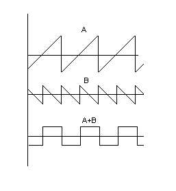
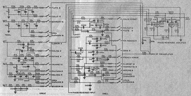
Once Kock had the harmonic spectra both of his generated waveforms and of the pipe sound he wished to imitate, he was able to derive a curve which specified the frequency response of the desired tone filter just by subtracting one from the other. His own electronics engineering knowledge plus that of colleagues such as Bode then enabled him to design a circuit with a frequency response approximating to that curve. As far as I know little or none of this work was ever published in the public domain, pivotal though it was for designing the tone forming filters in a musically acceptable electronic organ using subtractive synthesis. One can surmise that there were several reasons for this, commercial secrecy perhaps being one of them because Kock was by then involved with the Baldwin company of Cincinnati. Indeed it was they who funded his sojourn in India. The unfortunate consequence was that few other manufacturers had any idea how to design and optimise the voicing circuits used subsequently in their instruments, and this led to the best part of half a century in which the majority of analogue organs sounded utterly dreadful. As late as 1980 I was able to get some articles on tone filter design published in an internationally-read journal precisely because of this deficiency in the literature, not because they described anything particularly novel in terms of the technology employed [4]. In effect, this work reinvented and made public the theory underlying the tone filter circuits first employed in the Baldwin organ nearly 40 years earlier. However until I had done it I (and many others I suspect) had little understanding of why Baldwin’s tonal synthesis circuits were as they were, and in particular how their component values in terms of ohms, microfarads and henries had been derived. Some of Kock's original circuits eventually used in the Baldwin Model 5 organ are shown in Figure 10. It was interesting that the basic circuits I came up with independently for the various classes of organ tone turned out to be identical to those used by Baldwin: 1. Flutes required a 3rd order passive RC network; 2. Diapasons required a 2nd order passive RC network; 3. Strings required a bandpass network built from RC sections only; 4. Reeds required a bandpass network including LC sections. (Here components with resistance, capacitance and inductance are designated by R, C and L respectively in the usual manner). The reed circuits were particularly interesting because the use of LC sections, which resonated at certain frequencies, was necessary to simulate the formant bands found in both organ reed pipes and orchestral instruments including the woodwinds and brass. As mentioned above, Kock had pursued this in the 1930’s while doing his PhD research in Germany under the guidance of Wagner, Trautwein and others who first discovered formant phenomena and gave them their name. The Baldwin Piano Company of Cincinnati was a well regarded firm which had been making pianos since the 19th century, and in the 1930’s they had enough business nouse to spot the potential for a good but realistically priced electronic organ. One can probably emphasise the word “good” here, because Baldwin’s interest might have been sparked by the recent appearance of the Hammond organ. Although ground breaking in its way, the Hammond could not possibly simulate many organ pipe tones properly when only nine harmonics were available for additive synthesis. So it did not, has not and could never have simulated the sound of a pipe organ in other than a grossly inadequate manner despite the ludicrously exaggerated claims made at the time and since. Thus Baldwin employed their local-boy-made-good to do all the difficult technical stuff in subtractive synthesis for them. Returning from India in 1936, Dr Kock as he now was became Baldwin’s Director of Research while still in his mid-twenties, and he designed many aspects of their first electronic organ system which was patented in 1941. (Another important contributor was J F Jordan). Kock’s work at Baldwin was characterised by innumerable new ideas and innovations which one can see by surveying the firm’s patent output from that period [5]. To select just one example, let us discuss his well known “outphaser” circuit which produces a square wave from two sawtooths. Simple when you know how, it is nevertheless one of those ideas which needed rather a clever guy to first think of it. Kock realised that to simulate pipe sounds accurately you not only needed carefully designed filter circuits, but the waveform driving them had to be chosen properly as well – this in itself demonstrated the extent of his technical vision even though it is taken for granted today. Many organ tones require all harmonics to be present in the driving waveform, and a suitable waveform in this case is the sawtooth as produced by his neon tube oscillators. However, others need a preponderance of odd harmonics for which a square wave is more appropriate. Such tones have the “hollow” sound of the clarinet, vox humana and most flute pipes. Thus the question arose of how to derive both types of wave from his generator circuits. Although he could have added a complete and separate system to generate the square waves, this would have been clumsy and uneconomical given the limitations of the technology then available. Thus he arrived at an elegant and cost-effective solution which was described in his US patent number 2,233,948 of March 1941. Referring to Figure 3, A represents a sawtooth wave at the desired frequency. B is another sawtooth wave but different from A in three respects – it is only half the amplitude, has twice the frequency, and it is also phase-reversed. Adding A and B together then produces a square wave at the same frequency as A. It only has half the amplitude of A but this does not matter because this can be overcome by amplification as necessary.
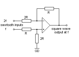
Figure 3. Kock’s “outphaser” method for deriving a square wave from two sawtooth waves. It is important that A and B are exactly phase locked, but this happened automatically in Kock’s tone generating system which used frequency division techniques. The method also needs sawtooth waves at two footages, but this also was catered for because his signal keying system used multi-gang switches for each note to cater for stops at the several footages required in an organ specification. But the really elegant feature of this circuit is that it works polyphonically, that is, you only need one of them for an entire keyboard regardless of how many notes are keyed simultaneously. The circuit is merely connected to two sawtooth keying buses an octave apart and it then generates all the necessary square waves automatically. The reason it works like this is because it is essentially nothing more than an analogue adder, a linear operation which therefore does not produce any nonlinear intermodulation distortion products between the frequencies that are keyed. Kock implemented it using two triode valves as can be seen at the top right corner of Figure 10, but for today’s engineers it is probably more meaningful to show how it could be built using a single operational amplifier. This is depicted at Figure 4, where two sawtooth signals an octave apart with frequencies f and 2f are applied to the inputs. (Yes, it does work too – I’ve tried it!). An important and useful voicing feature is that the proportions of the odd to even harmonics can be adjusted by varying one of the input resistors, because complete cancellation of the even harmonics never occurs for real organ pipes. The reason why the circuit came to be known as an “outphaser” is because the even-numbered harmonics in waveform A are exactly cancelled – “phased out” - by the phase-reversed odd-numbered ones in B, leaving only the odd harmonics in A. Baffled? It does show how clever he was though all those years ago, doesn’t it!
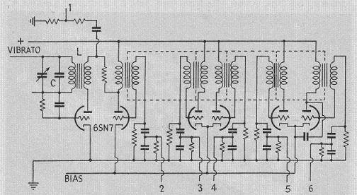
Figure 4. An op-amp realisation of Kock’s “outphaser”. When the USA entered the second world war presumably all thought of electronic organs was forgotten for the duration, and in Baldwin's case I believe their piano factory was commandeered to make prefabricated wood structures of some sort. Kock moved to Bell Telephone Laboratories where he was involved, like so many others on both sides of the Atlantic, on radar research. His particular speciality was microwave antennas (aerials) and he continued in this field for some years afterwards. Baldwin meanwhile brought out their first organ in 1946, just after the war had ended. Like everything else in science and engineering, it benefited considerably from the technical progress made during the war years. Although based largely on Kock’s pre-war designs, there was one major difference. It now used double-triode valves (octal-based 6SN7’s with two triodes in one glass envelope) instead of neon tubes. It was the war which had enabled high performance valves to be made sufficiently cheaply for the first time. Baldwin’s tone generation system was unique at the time, though its concept if not the detail was subsequently widely copied. It used twelve continuously-running stable master oscillators, each one tuned to a different note of the equally tempered scale (though any temperament could have been used). Each oscillator sent its own note to the keying system (described later), and it also drove a string of frequency dividers which produced the same notes but in successively lower octaves. Other than the fact they used valves rather than neon tubes, the frequency divider system concept remained based on Kock’s thinking. Normally a divide-by-two circuit produces a square wave, and the Eccles-Jordan flip-flop circuit for implementing this had been invented prior to 1920. However the lack of even numbered harmonics in a square wave makes it unsuitable for deriving most organ tones, so (as we have seen) Kock preferred to generate sawtooth waves which contain all harmonics. He then used his outphaser technique to reduce the even harmonic levels in those tones which required it. As with Kock’s earlier neon tubes, the Baldwin divider produced a close approximation to a sawtooth wave using just one triode section in a 6SN7, an economical arrangement. They were actually free running oscillators, but because they were designed as so-called blocking oscillators they could easily be synchronised to each other. By choosing the component values properly, each oscillator would run at exactly half the frequency of the one from which it was triggered, and in turn it would trigger the next one down the divider chain. The circuit of an oscillator with its retinue of dividers is shown in Figure 5.
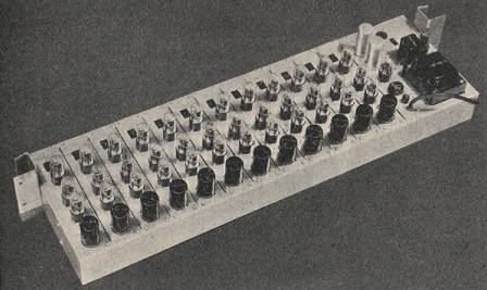
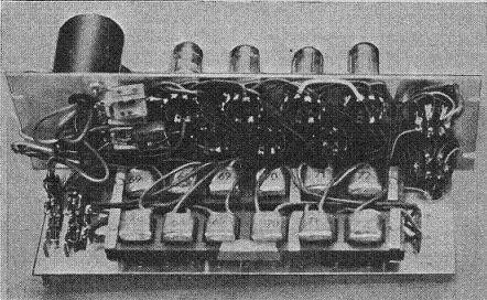
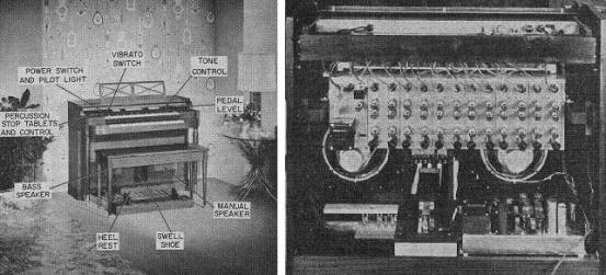
The tuneable oscillator is on the left and the successive dividers run to the right. Signals were tapped off and passed to the keying system as indicated by the numbers 1 to 6. A switchable vibrato (tremulant) signal, adjustable in depth and rate by the player, was injected into the oscillator as shown, varying its frequency cyclically. The dotted lines indicate the unique synchronising transformer developed by Baldwin, and more will be said about this later. For the smaller production organs complete tone generator assemblies were made in 6 octave versions, as per the circuit in Figure 5, generating 73 notes. This produced a complete range of frequencies from 16 to 8 foot pitch, although in these instruments an incomplete 4 foot rank was also derived in which the top octave broke back to 8 foot. Larger versions were also produced, and some of these also had more than one independent set of oscillators and dividers. A 73 note generator chassis is shown in Figure 6. Thirty seven 6SN7 valves were employed, driven by the large and potentially dangerous power supply unit seen at the right hand end. The valve heaters alone consumed nearly 25 amps at 6.3 volts, and the whole thing ran rather hot.
A curiosity of the Baldwin tone generator, referred to above when discussing the circuit in Figure 5, was the method employed to trigger the successive dividers. This used a transformer with multiple windings on a common lamination assembly as shown in Figure 7, which is a photograph of a generator sub-chassis as used in the larger organs. It is unclear to me why this method of synchronisation was used – it must have been an expensive way to do it, and anecdotal evidence suggests it was difficult to set up in the factory (thus making it even more expensive). The procedure involved the insertion and adjustment of magnetic shunts across the lamination stack. It is difficult to believe that our hero Winston Kock had any hand in this, particularly as he had by then left the firm for Bell Labs. It is a clumsy scheme showing none of the elegance and flair of his thinking which we see in other aspects of the design of the Baldwin organ.
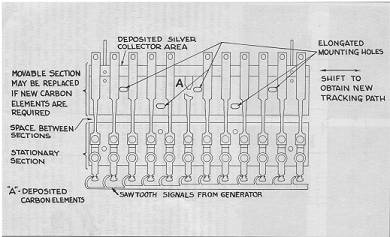
In an electronic instrument in which the oscillators do not run until a note is keyed, it is easy to introduce a gradual attack and decay to the sound. Although this does not imitate accurately the attack and release transients of all organ pipes, it approximates moderately well to those which do not have them in the first place. In any event, it is far better than not having any form of controlled attack and release at all. Thing were more difficult in an organ such as those by Baldwin in which the oscillators ran continuously. But, undaunted by the difficulties, from the outset they incorporated an advanced form of transient control using variable resistance keying. In this they were largely in a class of their own because few other analogue organs (at least those using frequency division) incorporated anything comparable. Like so much else in these instruments, the Baldwin keying technique was described and patented by Kock himself before the war. As the key was depressed, a curved metal strip progressively shorted out a carbon resistance element to provide a gradual rather than sudden attack (and decay) to the sound. No other instrument used this or any comparable technique at that time, and it endowed the Baldwin instrument with an unusually elegant sound which captivated many musicians of the day. A schematic of the key contacts as issued to Baldwin technicians is shown at Figure 8. Note that the stop switches as well as the key contacts themselves also used the gradual attack contact arrangement, thus stops seemed to "come on properly" as one reviewer described it.
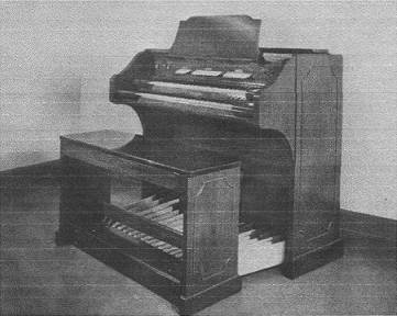
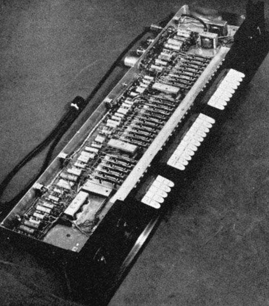
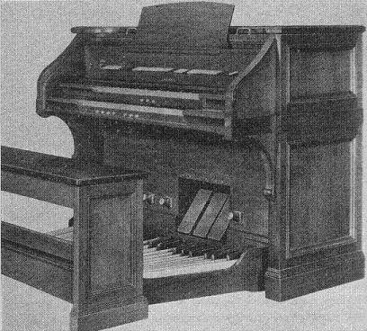
A large number of instruments using Kock’s technology were produced over some three decades, and the console of the Baldwin Model 5 is illustrated here in Figure 9. This appeared just after the war had ended. Its stop list is in Table 1, and Kock's circuits used for deriving these tones are shown at Figure 10 - these were accommodated in the tone chassis pictured in Figure 11. The stop keys operated the same type of gradual-attack switches used in the keying system as described above. Perhaps the most striking feature about the disposition is the large range of reeds available. This was not connected in any way with the difficulty or otherwise of producing them, as it mattered little in an engineering sense. Nor did it seem musically necessary to have so many in such a small instrument. It is possible this feature highlighted the business necessity of competing at that time with Baldwin’s major rival, Hammond. Although the Hammond organ could render a passable imitation of flutes and maybe some woolly diapasons with its nine harmonics (only seven if referring to synthesis at 8' pitch and progressively fewer at the higher ones), it was utterly hopeless when it came to strings and reeds. With these types of stop Baldwin’s subtractive synthesis technique with its large numbers of available harmonics would have come into its own. The elaborate Baldwin keying system might also have been aimed at highlighting the awfulness of Hammond's key clicks in the early models. Whatever the reasoning, the Baldwin models sold so well from the start that the company renamed itself the Baldwin Piano and Organ Company soon after. As to cost, the installed retail price of the Model 5 was $2650 in 1947. I am unable to say how this compared at the time with the Hammond organ or whether it would have been considered reasonable value for what was a small instrument.
Table 1. Stop list - Baldwin Model 5
Figure 10. Tone circuits - Baldwin Model 5
Figure 11. Tone circuit chassis - Baldwin Model 5
A range of larger models also appeared. The Model 10 is shown in Figure 12 and its stop list at Table 2. In addition to the two expression pedals (each of which had an indicator and which could be coupled together via a switch) there was also a crescendo pedal. The combinations on the pistons could be instantly captured by means of a motor-driven switching and memory system, the only electronic organ then available with this facility.
Table 2. Stop list – Baldwin model 10 By the 1960’s Baldwin were just one of many manufacturers making organs using subtractive synthesis, the majority of which were heavily targeting the domestic market. Without compromising on their major tonal features, including their laudable keying system, Baldwin offered cheaper models such as the 45 which is shown in Figure 13. The stop list at Table 3 shows it was little different in scope to that of the original Model 5, merely having some concessions to an “entertainment” specification.
Table 3. Stop list – Baldwin Model 45H
However the firm did not abandon the higher-quality classical organ market in the 1960's. No doubt building on the experience gained with the Model 10 a decade earlier (see above), they brought out the Model 11, impressive for its day, whose stop list is shown in Table 4. Unlike the Model 45 and others produced up to that time, this was a hybrid instrument using both valves and transistors. It had detuned (undulating) stops on both manual divisions, which means it must have had at least two independent ranks of tone generators. Some anecdotal evidence suggests there were in fact five ranks in total, two of which serviced the detuned stops. Therefore it is likely the generators were transistorised if only so that they would have fitted inside the console, with the power amplifiers (also probably five in number) continuing to rely on valves. This hybrid arrangement (solid state circuitry for small signals and thermionics for power) was common in much audio equipment in the mid-twentieth century. The Model 11 was well-liked, and some recordings made on it by the late Virgil Fox could be found on the Internet at the time of writing (early 2014) [6].
Table 4. Stop list - Baldwin Model 11
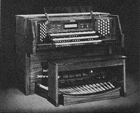
As late as the 1970’s, well into the era of the Allen digital organ, Baldwin were still offering quite large church organs using essentially the same analogue technology as that invented by Winston Kock before the war. Of course, this was forced on them owing to the strength of the Allen patents, and in this they were in the same position as all other manufacturers. This stranglehold did not relax until the 1990’s when the Allen patents expired. A typical Baldwin product of the mid-1970’s, which by then was using all solid state circuitry, is shown in Figure 14.
I have played Baldwin organs at a time when they were still marketed and in my opinion, for what it is worth, they were pretty good in relative terms. That is to say, they sounded significantly better on the whole than the general run of analogue organs by other manufacturers, and they were only beaten by a few custom built instruments in which cost was not a factor. It would not be true to say they sounded as good as a good digital organ today, but they compared favourably with the early Allen digitals in the 1970's. Nor, of course, did they sound indistinguishable from a pipe organ, but that is true for all pipeless organs. To my ears they also sounded much better and more natural than the cloying tone of the more expensive Compton Electrone which, like the Hammond, also relied on attempts at additive synthesis with insufficient numbers of harmonics.
Today one occasionally hears comments that they sounded like 'comb and paper'. Although this was true of the majority of mass produced analogue organs by other manufacturers in their day, a Baldwin organ in good condition was significantly better. Such remarks usually arise on Internet chat forums in the context of old instruments which have been switched on for the first time following years or decades of neglect, and in the case of the Baldwin organ there is often a good reason for the defect in these cases. Over time it can arise owing to the large number of multi-pin plugs and sockets which were used to facilitate servicing - the pins and receptacles of these can become dirty or corroded. It is essential that ground (earth) line impedances in an assembly as complex as the Baldwin organ are maintained at negligibly small values, otherwise the plethora of high-amplitude sawtooth signals flying around the system can find their way directly into the amplifier inputs. Simply 'jiggling' the connectors (and the valves/tubes themselves) can result in a marked improvement, although this is not an alternative to a proper service and overhaul by someone who knows what they are doing. Some recordings of reasonable quality still exist of the instrument, and the late Virgil Fox was reportedly one of its fans. For example, he recorded many pieces on Command Records number 15401, some tracks from which can be heard on YouTube (see note [6] for some links). None of these sound remotely like 'comb and paper', indeed the instrument sounds distinctly respectable. Thus it is not difficult to see why the Baldwin organ became a commercial winner so quickly in the 1940s when its only significant rival was the Hammond organ.
The Baldwin keying arrangement was undoubtedly a factor which contributed to their success, and because I was aware of how it worked I was interested to experiment with it. It had some degree of touch sensitivity which a clever player could exploit, just as in a good mechanical action pipe organ where the speed of key attack and release can influence the transient emitted. No electronic organ today offers this feature. I recall the very faint "clattering" sound which you could just hear if you were listening for it as the keying wipers touched the resistive elements, though it was not a problem in normal playing. Nevertheless, in the production models there were two major design compromises in the interests of economy, although these also applied to many other analogue organs as well as the Baldwin. The first was that, as we have seen, individually tuneable oscillators were not used. There were only 12 independently tuned oscillators, one for each semitone of the top octave, with all other notes derived by frequency division. Only in the larger and more costly custom models were sufficient numbers of independent tone sources made available. The second design compromise was that only a single tone circuit was used for each stop. This meant that, while the sounds were reasonably good in the middle of the keyboard, they became progressively unrealistic towards its extremities. The formant concept cannot be carried too far when simulating the pipe organ, because unlike an orchestral instrument such as an oboe which has a single formant structure, a rank of organ reed pipes has formants which vary across the compass. Therefore one should adopt Bode's "travelling formant" concept in subtractive synthesis, in which each stop or voice has several filter circuits. Each circuit operates over its own region of the keyboard. Only a few of the most elaborate analogue organs incorporated this feature, and to the best of my knowledge Baldwin only used it in their flagship products such as the Model 11. Aside from these issues, the Baldwin organ was nevertheless one of the first to combine affordability with a very respectable sound for its time. It sounded far more like a pipe organ than anything which had been produced to date, including of course the Hammond organ of the 1930’s and the few reed organs which continued to be made. The principles of the Baldwin organ were widely copied, though the firm had tied up the patent situation to such a degree that direct copies were not marketed. Nevertheless many firms worldwide continued to make divider organs of one sort or another using subtractive synthesis until nearly the end of the 20th century, though hardly any of them incorporated any form of transient suppression as used by Baldwin from the outset. For this reason alone they were grossly inferior. Original Baldwin organs are rare now, partly because it is difficult to get them to work as they did originally. The main difficulty today is in overcoming keying problems, as the resistive elements would wear out over some years of use and the key contact assemblies are virtually unrepairable. While Baldwin supported these organs, their technicians surmounted this problem by replacing octave sections of the key contact stacks with factory substitutes. After the war Kock remained at Bell Labs to work on microwaves as we have remarked, but there is evidence that he also did some further work on tone filters for Baldwin either formally (i.e. under contract between Baldwin and Bell) or informally. He also did sonar research, and in the mid-1950’s he took a senior position in the Bendix Corporation which was active in underwater defence technology. He moved again to become NASA’s first Director of Engineering Research, returning to Bendix in 1966 where he remained until 1971. That year he became Acting Director of the Hermann Schneider Laboratory of the University of Cincinatti. Kock was a prolific writer and his publications are as varied as they are interesting. His book The Creative Engineer [1] set forth his belief that the most innovative engineers are those who, like himself, have multi-disciplinary interests. His fictional novels, such as Love’s Warm Sun, were written under the pseudonym Wayne Kirk. It is difficult to avoid the conclusion that this gentle tale was autobiographical. The book also contains songs which he composed. He wrote six books in all and is credited with 235 patents.
His contributions to the scientific literature were numerous, both in the form of papers presented at conferences and, more importantly, those published in respected peer-reviewed journals such as the Journal of the Acoustical Society of America. He never returned to electronic music having left Baldwin's, but there is no evidence of acrimony and the likelihood is that his fertile mind remained permanently whetted by the expansion of his intellectual horizons which he experienced at Bell Labs during the war years. Although like most gifted scientists and engineers he eventually rose to various senior management positions, unlike most of them he continued to be scientifically productive at the same time. It is clear that a field which captured his imagination and in which he did original research was acoustic holography. This was an outgrowth of some work he did on microwave lens antennas, probably during the war, and he is also credited with the creation of what are now known as meta-materials with a negative refractive index. These are now being intensively researched for use in several applications, including making military targets invisible. It would be inappropriate to expand this summary further in an article whose purpose is to highlight his contributions to electronic music, and those interested need only type his name into Google whereupon it will become clear that in a sense he still lives through the work he did. Unfortunately the same search will reveal next to nothing about his work in electronic music, therefore this article has attempted to set the record straight in this regard.
Kock comes across as a kindly and avuncular man with a strong sense of the importance of family life, a good work-home balance and a practicing Christian. Although well known and highly qualified, he nevertheless seemed to derive much pleasure from the smaller things in life such as his High School certificates and being elected an Elder of his local church. Therefore in many ways he typifies the best of the spirit of America through his work ethic, his beliefs and the way he made the most of every opportunity which came his way. Today's world can learn something from such men. Winston Kock died in 1982 after a life crammed with achievement and creativity in many fields. It is extraordinary that most accounts of electronic music mention the importance of the Baldwin organ, but few acknowledge the key role he played in bringing it to the marketplace. It is mainly for this reason that this article was written. Perhaps it is because he spent the post-war years doing other things, but it seems reasonable to conclude that he has a place in history which is well deserved. 1. “The Creative Engineer”, Winston E Kock, Plenum Press, New York 1978. ISBN 0 306 30987 4. Subtitled “The Art of Inventing”, this book of nearly 400 pages is a fascinating review of the art, science and engineering with which Kock was involved during his career. Written towards the end of his life, it reveals much of his philosophy on subjects ranging from religion to child-rearing and it also contains a significant autobiographical element. I have drawn heavily on it during the compilation of this article. 2. British Patent 15,245, 1890, Robert Hope-Jones. This visionary document, conceived and written years before a shred of the necessary enabling technology was available, antedates by a quarter of a century the patents of Thaddeus Cahill for his monstrous Telharmonium, and by several decades those of Hammond and Compton for their respective additive synthesis instruments. All of them describe rotating tone wheel generators to produce the individual harmonics of musical sounds, but Hope-Jones had beaten them all to it. 3. “Acoustic Spectra of Organ Pipes”, C P Boner, J Ac Soc Am, July 1938, p 32. 4. “Tone Filters for Electronic Organs”, C E Pykett, Wireless World, October and December 1980. These articles are summarised and can also be downloaded in full here. 5. Kock’s first patent was US patent 2,046,463 dated July 1936, detailing the outcomes of his PhD work in Germany on improving the stability of neon discharge tube oscillators. Subsequent ones related to the Baldwin organ include US patent 2,139,023 of December 1938 entitled “Electrical Generation of Musical Tones”. It describes the use of formants to simulate musical tones, and neon glow discharge oscillators with which to drive them. Another is US patent 2,233,948, March 1941, containing a complete description of the multiple tone forming circuits used in the first Baldwin organ. Other US patents filed by Baldwin with Kock identified as patentee include numbers 2,148,478; 2,185,653; 2,215,124 and 2,230,429. Baldwin also filed vigorously in other countries including the UK, where typical patents include numbers 527,080 and 539,752.
6. Some recordings by Virgil Fox on a Baldwin organ can be heard on YouTube at the time of writing:
|